Supergravity regeneration device and system for establishing temperature gradient

A temperature gradient and regeneration device technology, which is applied in separation methods, products, and dispersed particle separation, etc., can solve the problems of enhanced corrosion of equipment and high concentration of lean amine solution, and achieve improved purity, reduced corrosion, and increased contact time. Effect

Pending Publication Date: 2022-05-31
QINGDAO HEADWAY TECH
View PDF0 Cites 0 Cited by
  • Summary
  • Abstract
  • Description
  • Claims
  • Application Information

AI Technical Summary

Problems solved by technology

Moreover, the concentration of the lean amine solution flowing out of the reg...

Method used


Image

  • Supergravity regeneration device and system for establishing temperature gradient
  • Supergravity regeneration device and system for establishing temperature gradient

Examples


Embodiment 1

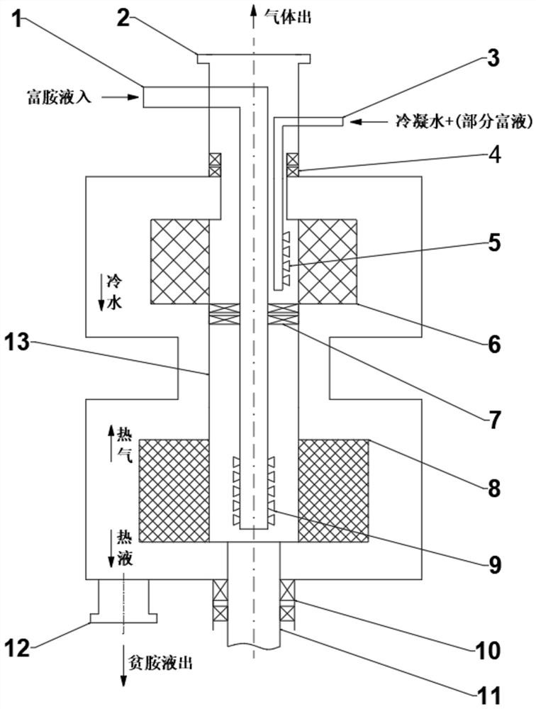
[0032] Embodiment one, such as figure 1 As shown in - 2, a high-gravity regeneration device for establishing a temperature gradient according to an embodiment of the present invention includes a casing, a gas outlet 2 is set at the center of the top of the casing, and a lean Amine liquid outlet 12, a hollow rotating shaft 13 is provided at the center of the housing axial direction, the top of the hollow rotating shaft 13 communicates with the gas outlet 2, and the bottom of the hollow rotating shaft 13 communicates with the solid rotating shaft 11 Fixedly connected, the other end of the solid rotating shaft 11 penetrates to the outside of the housing to connect with the motor, and the two sides of the outer surface of the housing near the end of the gas outlet 2 are respectively inserted with a rich amine liquid infusion tube 1, a condensation Water pipe 3, the ends of the rich amine liquid pipe 1 and the condensed water pipe 3 go deep into the hollow rotating shaft 13, and th...

Embodiment 2

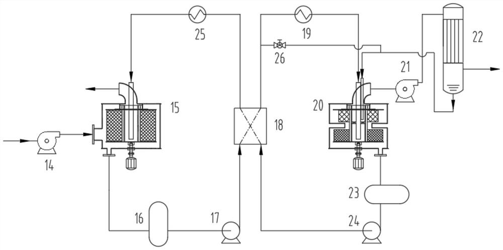
[0036] Embodiment two, such as figure 1 - As shown in 2, a high-gravity regeneration system for establishing a temperature gradient according to an embodiment of the present invention includes a high-gravity regeneration device 20, a first axial flow fan 14, a high-gravity absorption device 15, a rich liquid tank 16, and a rich liquid transport Pump 17, lean-rich liquid heat exchanger 18, rich-liquid heater 19, second axial flow fan 21, condenser 22, lean-liquid tank 23, lean-liquid delivery pump 24, ice machine 25, rich amine liquid regulating valve 26, The supergravity absorbing device 15 is respectively connected with the first axial flow fan 14, the ice machine 25, and the rich liquid tank 16, and the rich liquid tank 16 is connected with the rich liquid delivery pump 17, and the The rich liquid delivery pump 17 is connected to the lean-rich liquid heat exchanger 18, and the high-gravity regeneration device 20 is connected to the rich liquid heater 19, the second axial flo...


PUM


Abstract

The invention discloses a supergravity regeneration device and system for establishing a temperature gradient, the supergravity regeneration device comprises a shell, a gas outlet is arranged in the center of the top of the shell, a lean amine liquid outlet is arranged on one side of the bottom of the shell, a hollow rotating shaft is arranged in the center of the axis direction of the shell, and a gas inlet is formed in the middle of the shell. The shell is provided with a gas outlet, the top of the hollow rotating shaft is communicated with the gas outlet, the bottom of the hollow rotating shaft is fixedly connected with a solid rotating shaft, and the other end of the solid rotating shaft penetrates through the outer side of the shell to be connected with a motor. Firstly, carbon dioxide moves upwards along with a gas phase and passes through an S-shaped gas-liquid heat exchange area in the middle, and part of water vapor in the gas phase is condensed; afterwards, the gas phase reversely flows into an upper packing layer and exchanges heat with condensed water; and removing part of easily-coagulated components in the gas phase again.

Description

technical field [0001] The invention relates to the technical field of carbon dioxide capture, in particular to a high-gravity regeneration device and system for establishing a temperature gradient. Background technique [0002] The principle of high-gravity regeneration technology is to use centrifugal force to throw the material out of the rotating bed at high speed for the multi-phase process that needs to strengthen the inter-phase transfer process and the mixing and reaction process that needs micro-mixing and strengthening in the phase or quasi-homogeneous phase. During this process, the huge shear stress overcomes the surface tension, and the liquid is dispersed and broken by the filler to form a huge, constantly renewed surface area. In this way, excellent mass transfer and reaction conditions are formed inside the rotor. Materials can be co-current, counter-current or cross-flow. [0003] However, the gas-liquid parallel flow mode is adopted in the traditional car...

Claims


Application Information

Patent Timeline
IPC IPC(8): B01D53/62B01D53/78B01D53/96
CPCB01D53/78B01D53/62B01D53/96B01D2257/504Y02P20/151
Inventor 曹学磊谢湘平李志刘炳言胡振华王建春阎成伟房召祥王青青林洪健冯展光
Owner QINGDAO HEADWAY TECH
Why Eureka
Try Eureka