Data readers

a data reader and data technology, applied in the field of data readers, can solve the problems of poor yield in the fabrication process, difficult to achieve over the whole frequency range, and difficult to achieve the corners of the fabrication process, and achieve the effect of accurate reading

Inactive Publication Date: 2005-12-13
HEWLETT-PACKARD ENTERPRISE DEV LP
View PDF9 Cites 5 Cited by
  • Summary
  • Abstract
  • Description
  • Claims
  • Application Information

AI Technical Summary

Benefits of technology

[0032]The method may comprise performing a self calibration routine in which the processor adjusts values contained in the look up table / adjusts the predetermined function to help ensure that the cut-off frequency of the filter is correctly controlled relative to the velocity of the data holding medium. This helps to ensure that data can be accurately read from the data-holding medium.
[0033]Conveniently, the filter is arranged to provide gain to a signal fed thereto in a region of the cut-off frequency. This helps to equalise the signal to the desired signal characteristics.

Problems solved by technology

This can be difficult to achieve over fabrication process corners and for the whole frequency range.
These difficulties call result in a poor yield in the fabrication process.

Method used


Image

  • Data readers
  • Data readers
  • Data readers

Examples


Embodiment Construction

with reference to the accompanying drawings of which:

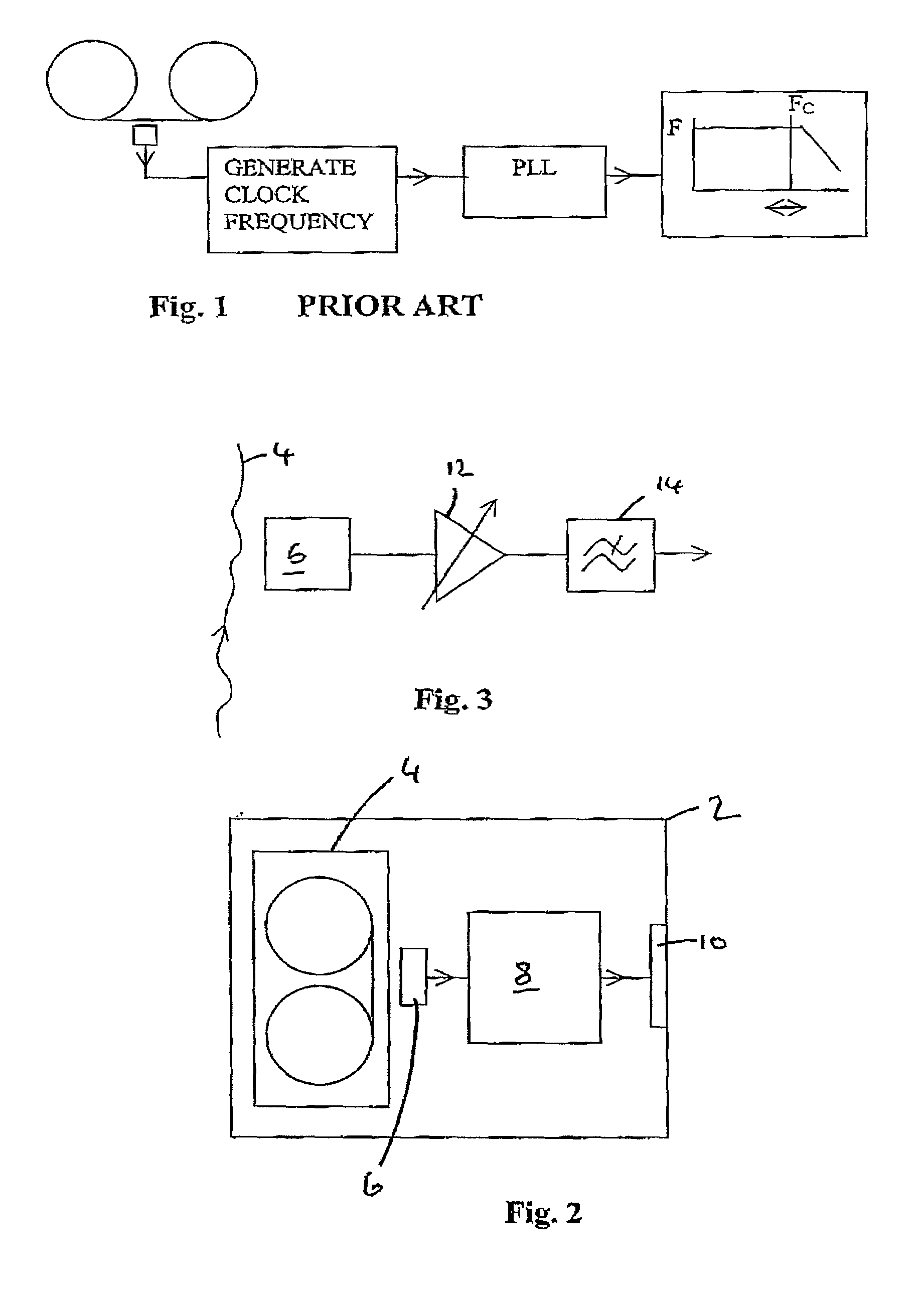
[0036]FIG. 1 is a diagram of a prior art arrangement for processing a signal read from a magnetic tape;

[0037]FIG. 2 is a diagram of the main components of a storage device;

[0038]FIG. 3 is a schematic view of an arrangement for initially processing a signal produced on reading a magnetic tape;

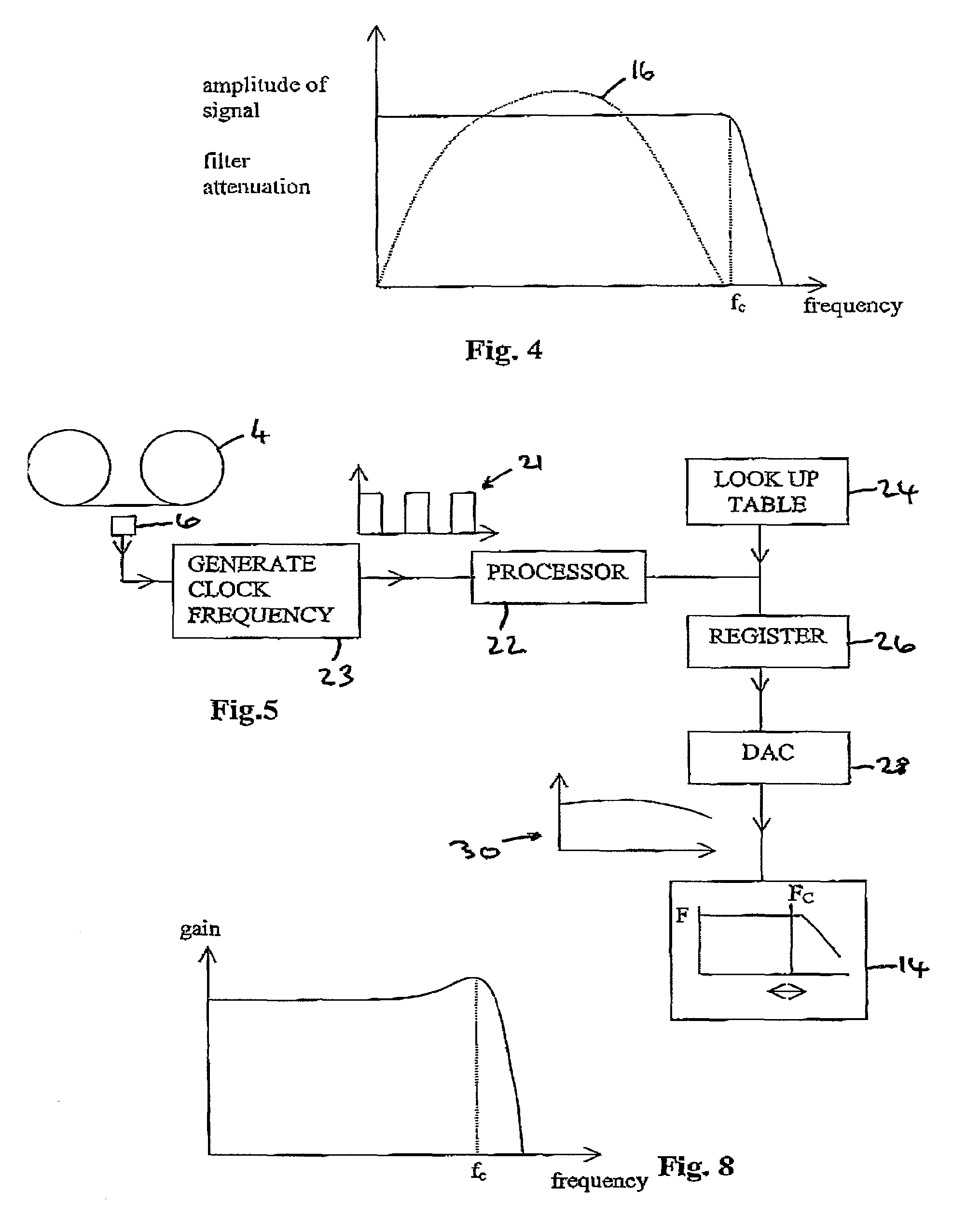
[0039]FIG. 4 includes plots of amplitude versus frequency of the frequency response of a low pass filter and the amplitude of the signal produced on reading the magnetic tape;

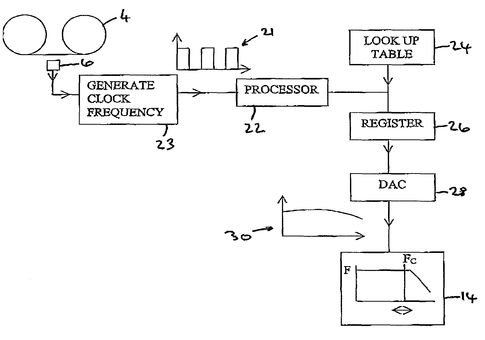
[0040]FIG. 5 is a block diagram of the components for initially processing a signal produced on reading the magnetic tape according to a preferred embodiment of present invention;

[0041]FIG. 6 is a flow chart of how the components shown in FIG. 5 are controlled;

[0042]FIG. 7 is a schematic diagram of the layout of a magnetic tape capable of being read by the structure of FIG. 5;

[0043]FIG. 8 is a plot of the gain versus frequency of a low pass filter.

DETAILED DESCRIPTION OF ...


PUM

PropertyMeasurementUnit
cut-off frequencyaaaaaaaaaa
speedaaaaaaaaaa
cut-off frequenciesaaaaaaaaaa

Abstract

A data reader derives a signal on reading a data holding medium. The data reader has processing circuitry to process the signal. The processing circuitry includes a filter having a variable cut-off frequency, a velocity signal generator that produces a signal corresponding to the velocity of the data holding medium, and a processor. The reads the velocity signal and sets the filter cut-off frequency. Calibration data derived during a calibration operation of only the particular data reader determines the filter cut-off frequency for different speeds of the medium during normal read operations of the medium.

Description

FIELD OF THE INVENTION[0001]This invention relates to an improved data reader and an improved method of reading data. It is particularly applicable to data storage devices, but may have wider applicability.BACKGROUND ART[0002]Early magnetic tape storage devices moved the magnetic tape past read heads at a fixed velocity. A low pass filter is provided within the decoding circuitry that removes unwanted high frequency noise. Because the tape passes the read head at a fixed velocity a signal produced by reading data read from the tape has a knowing maximum frequency. Therefore, the cut off frequency of the low pass filter can be set to ensure all of the signal passes the filter.[0003]It is now known to produce magnetic tape storage devices in which the velocity of the tape past the read bead is varied. Varying the velocity in this manner helps to ensure that the rate of data transfer to and from the tape can match the rate of data transfer to the storage device. This matching of data r...

Claims


Application Information

Patent Timeline
Patent Type & Authority Patents(United States)
IPC IPC(8): G11B5/008G11B20/10G11B27/32
CPCG11B20/10G11B27/32G11B5/00813G11B2220/90G11B2220/913
Inventor WALSH, PETERJIBRY, RAFEL
Owner HEWLETT-PACKARD ENTERPRISE DEV LP
Why Eureka
Try Eureka