Resilient clip fastener

Inactive Publication Date: 2005-12-20
NEWFREY
View PDF38 Cites 68 Cited by
  • Summary
  • Abstract
  • Description
  • Claims
  • Application Information

AI Technical Summary

Benefits of technology

[0004]In another form, the present invention provides a resilient clip for use in securing a first structure to a second structure. The resilient clip includes a retaining portion having an engagement tab, which terminates at a load distributing element, and first and second wing members on opposite sides of the engagement tab. Each of the first and second wing members terminates at an engagement edge that is skewed to an axis along which the retaining portion is to be inserted through a hole in one of the first and second structures. The retaining portion is configured such that the engagement edges of the first and second wing members co-engage an edge of the hole at a location along a length of their engagement edge. The retaining portion is further configured so that the load distributing element contacts the one of the first and second structures in response to application of a withdrawing force to the resilient clip so as to increase an area over which the withdrawing force is applied relative to the engagement edges alone.

Problems solved by technology

One drawback of this configuration is that a withdrawal force applied to the clip fastener is distributed over a correspondingly small area.

Method used


Image

  • Resilient clip fastener
  • Resilient clip fastener
  • Resilient clip fastener

Examples


Embodiment Construction

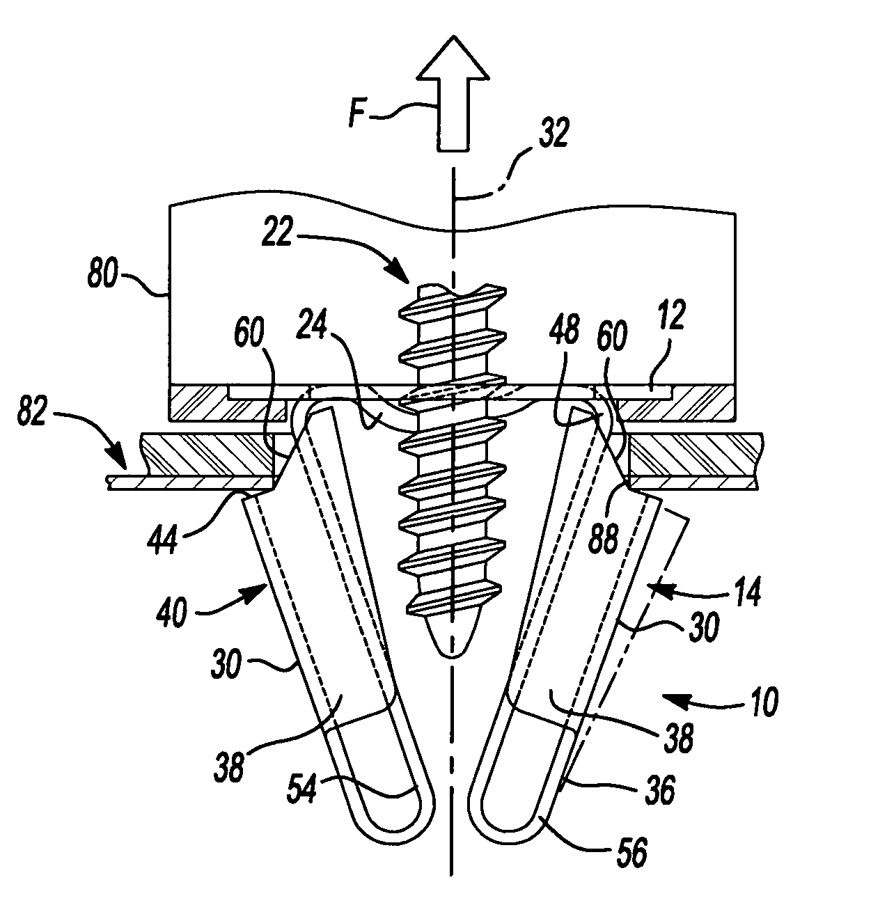
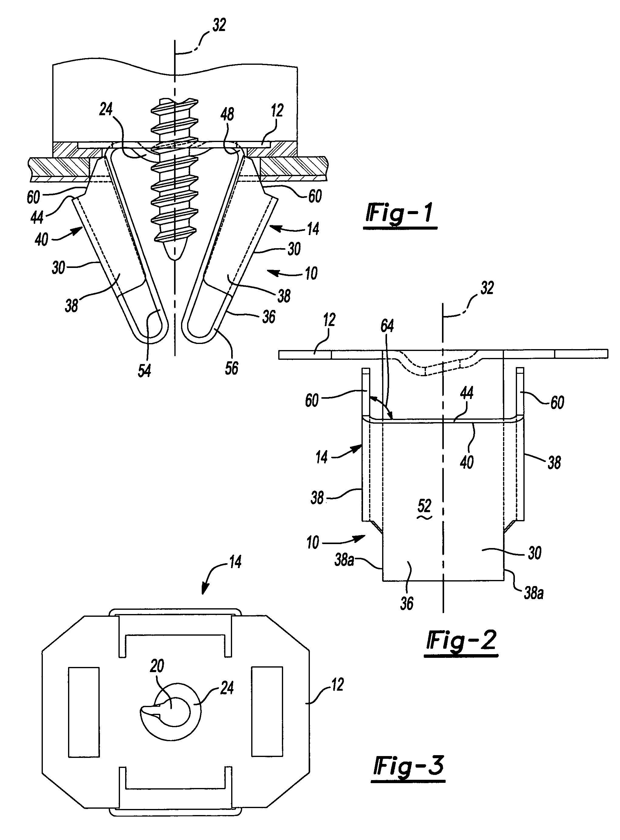
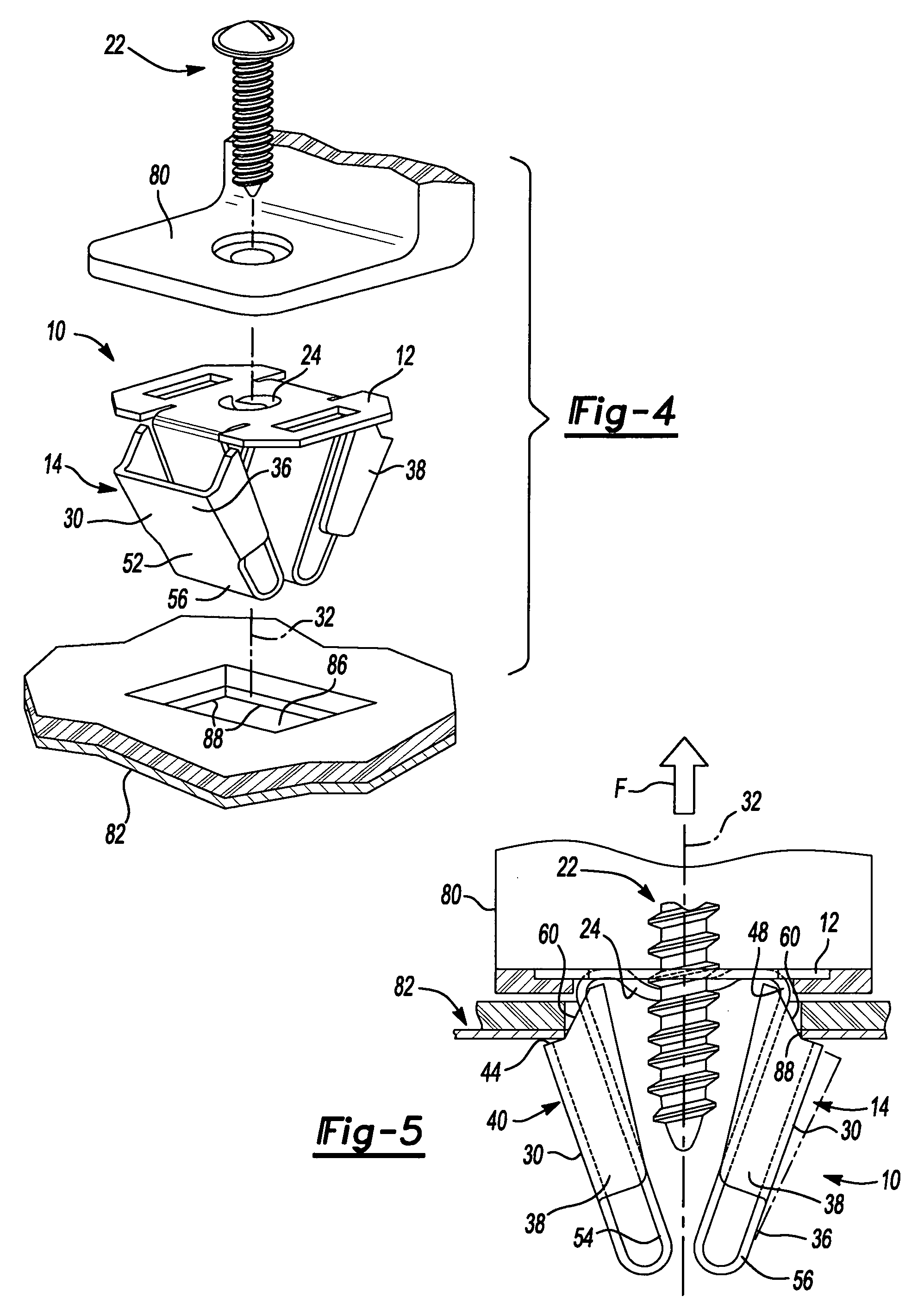
[0016]With reference to FIGS. 1 through 3 of the drawings, a fastener or resilient clip constructed in accordance with the teachings of the present invention is generally indicated by reference numeral 10. In the particular example provided, the resilient clip 10 is unitarily formed from a sheet metal material and includes an installation flange 12 and a retaining portion 14.

[0017]The installation flange 12 is generally planar and includes an aperture 20 for receiving therethrough a conventional threaded fastener 22 (FIGS. 4 and 5). In the particular embodiment illustrated, the aperture 20 is generally key-hole shaped, with a helical lip 24 for engaging the threads of the threaded fastener 22.

[0018]The retaining portion 14 includes a pair of engagement structures 30 that are located on opposite sides of an insertion axis 32 along which the resilient clip 10 is to be installed. Each engagement structure 30 includes an engagement tab 36 and a plurality of wing members 38.

[0019]The eng...


PUM


Abstract

A resilient clip having an engagement tab, which terminates at a load distributing element, and wing members that are configured to co-engage a structure to which the resilient clip is to be coupled. The wing members terminate at an engagement edge and are configured to co-engage the structure at a location along a length of their engagement edge. The load distributing element being configured to contact the structure in response to application of a withdrawing force to the resilient clip so that the load distributing element increases an area over which the withdrawing force.

Description

FIELD OF THE INVENTION[0001]The present invention generally relates to resilient clip fasteners and more particularly to resilient clip fasteners that employ a plurality of wing members to secure the resilient clip fastener to a structure. More specifically, the present invention relates to a resilient clip fastener having a construction that utilizes wing members and engagement tabs to permit the fastener to be inserted with a relatively low insertion force while resisting relatively high withdrawal forces in a manner that distributes the withdrawal force over a relatively large area.BACKGROUND OF THE INVENTION[0002]Clip fasteners of the type that employ wing members to engage the edge of a hole in a structure are known in the art. Such clip fasteners have relatively small areas of engagement with the structure to which they are attached, which tends to reduce the force needed for the installation of the clip fastener to the structure. One drawback of this configuration is that a w...

Claims


Application Information

Patent Timeline
Patent Type & Authority Patents(United States)
IPC IPC(8): F16B5/06B60N3/02B60R13/02F16B19/00F16B37/04
CPCB60N3/026B60R13/0206F16B37/043Y10T24/307Y10T24/303Y10T24/304
Inventor MACPHERSON, TERRENCE B.SLOBODECKI, JEFFREY A.
Owner NEWFREY
Why Eureka
Try Eureka