
Surgical stapler

a stapler and surgical technology, applied in the field of surgical staplers, can solve the problems of increasing the time, complexity and overall cost of laparoscopic surgical procedures, and the cost of designing and manufacturing multiple stapler sizes, rather than creating, and achieve the effect of convenient removal and engagemen

Inactive Publication Date: 2006-01-17
TYCO HEALTHCARE GRP LP
View PDF205 Cites 2271 Cited by
  • Summary
  • Abstract
  • Description
  • Claims
  • Application Information

AI Technical Summary

Benefits of technology

The patent describes a surgical stapling device that can be used in endoscopic or laparoscopic procedures. The device has a unique feature in that it can use different disposable loading units with different lengths of staple rows. The device includes a handle assembly with an elongated barrel portion and an actuation shaft that drives the actuator through a predetermined linear distance. The actuation shaft has a toothed rack and a pawl member for selectively engaging the toothed rack and advancing the actuation shaft in response to manipulation of the actuation handle. The device can be used with disposable loading units that have linear rows of staples and an anvil for forming staple lines with a particular linear dimension. The actuation shaft can be selectively engaged or disengaged with the engagement hook to maintain a particular linear position during an actuation stroke. The device also includes a release mechanism for manual disengagement of the engagement hook and a retracting mechanism for manual retraction of the actuation shaft.

Problems solved by technology

Such practices increase the time, complexity and overall costs associated with laparoscopic surgical procedures.
In addition, costs are greater in designing and manufacturing multiple stapler sizes, as opposed to creating a single, multipurpose stapler.

Method used


Image

  • Surgical stapler
  • Surgical stapler
  • Surgical stapler

Examples


Embodiment Construction

[0080]In the drawings and in the description which follows, the term “proximal”, as is traditional, will refer to the end of the stapling apparatus which is closest to the operator, while the term “distal” will refer to the end of the apparatus which is furthest from the operator.

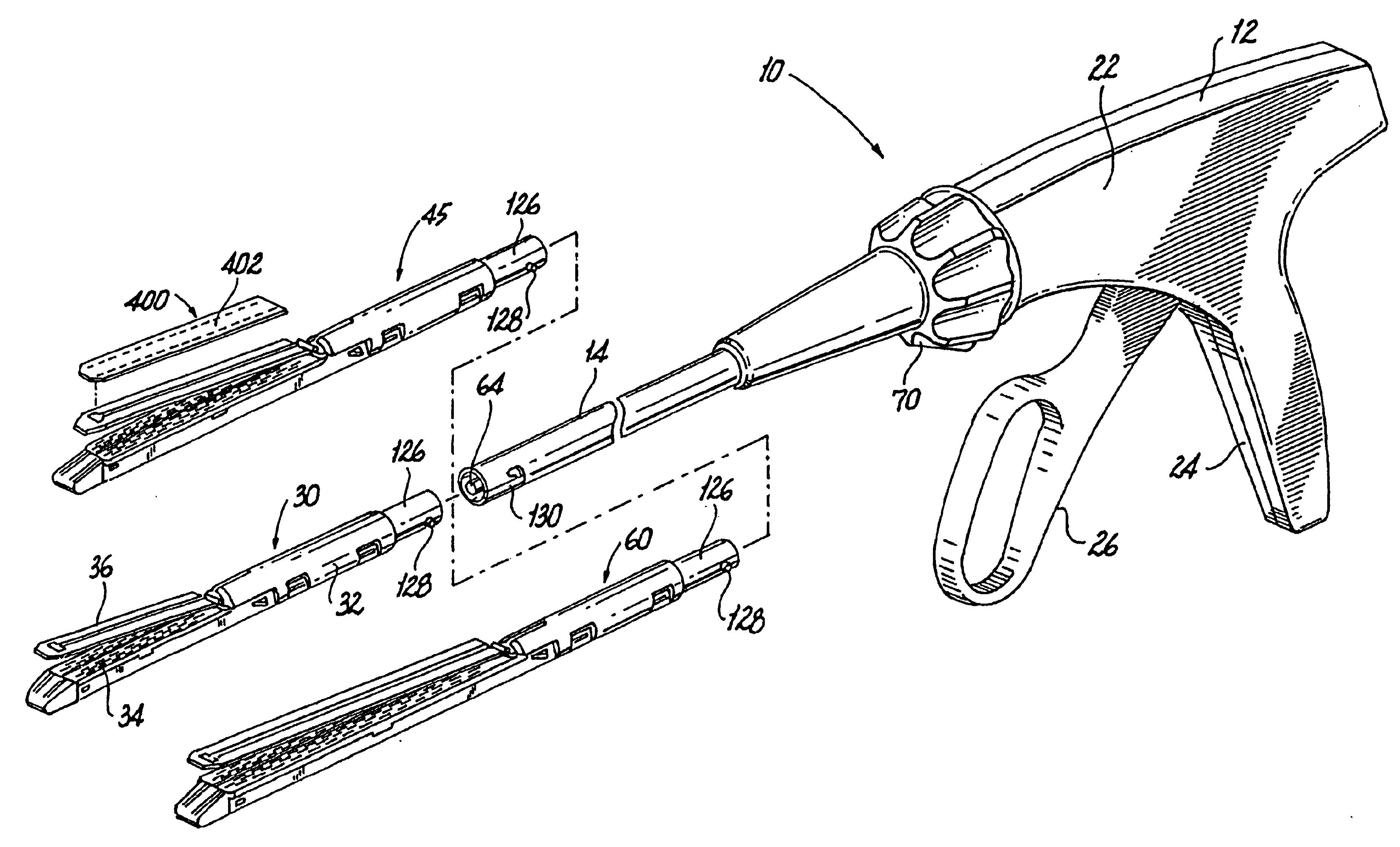
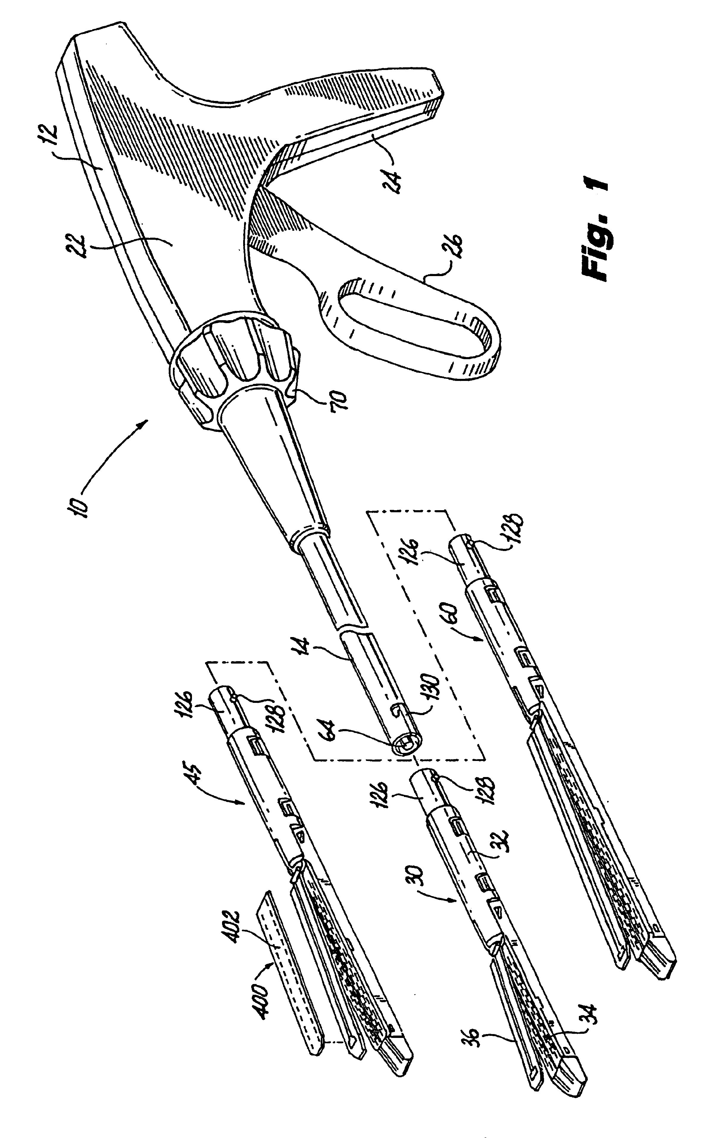
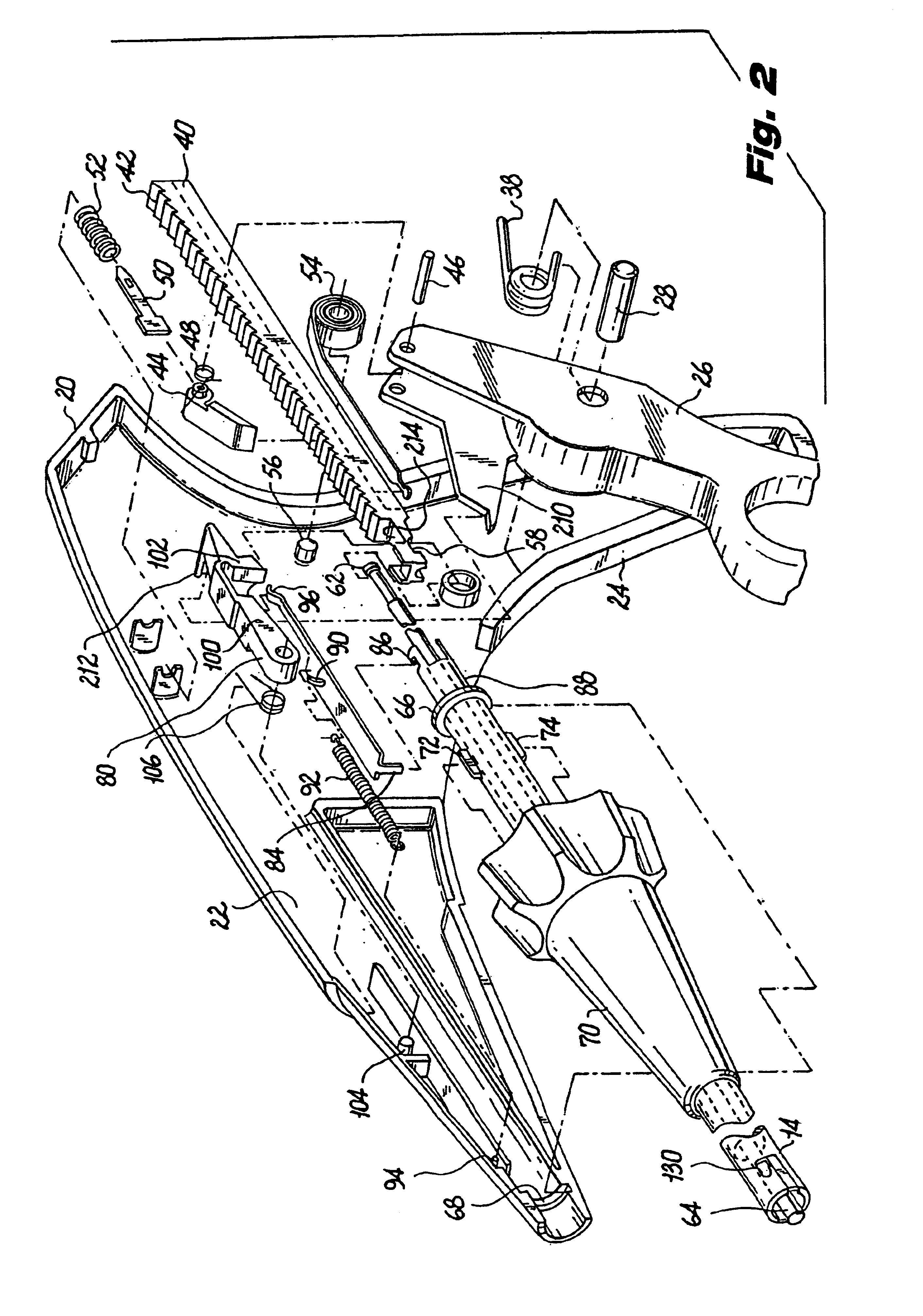
[0081]Referring now to the drawings wherein like reference numerals identify similar structural elements of the subject invention, there is illustrated in FIG. 1 a surgical apparatus constructed in accordance with a preferred embodiment of the subject application and designated generally by reference numeral 10. In brief, surgical apparatus 10 is a surgical stapling apparatus configured to engage body tissue, apply a plurality of surgical fasteners thereto, and form an incision in the fastened body tissue during a laparoscopic surgical procedure. Apparatus 10 can also be used to apply surgical clips and other fasteners (discussed in greater detail below) but will be primarily discussed in the context of app...


PUM

PropertyMeasurementUnit
lengthaaaaaaaaaa
lengthaaaaaaaaaa
lengthaaaaaaaaaa

Abstract

A surgical device is described herein that can be used to fire different types and sizes of disposable loading units. In a preferred embodiment, the device applies parallel rows of surgical fasteners to body tissue and concomitantly forms an incision between the rows of staples during an endoscopic or laparoscopic surgical procedure. The device can be utilized with disposable loading units configured to apply linear rows of staples measuring from about 15 mm in length to about 60 mm in length and can be used to fire disposable loading units containing surgical clips and individual staples.

Description

CROSS-REFERENCE TO RELATED APPLICATION[0001]This application is a continuation of U.S. application Ser. No. 09 / 497,647 filed Feb. 3, 2000, now abandoned, which is a continuation of U.S. application Ser. No. 09 / 119,543, filed Jul. 20, 1998, now U.S. Pat. No. 6,032,849, which is a continuation of U.S. application Ser. No. 08 / 546,253, filed Oct. 20, 1995, now U.S. Pat. No. 5,782,396, which is a continuation-in-part of copending U.S. application Ser. No. 08 / 520,202 filed Aug. 28, 1995, now U.S. Pat. No. 5,762,256.BACKGROUND[0002]1. Technical Field[0003]This application relates to a surgical stapling apparatus, and more particularly, to an apparatus for sequentially applying a plurality of surgical fasteners to body tissue and optionally incising the fastened tissue.[0004]2. Background of Related Art[0005]Surgical devices wherein tissue is first grasped or clamped between opposing jaw structure and then joined by surgical fasteners are well known in the art. In some instruments a knife i...

Claims


Application Information

Patent Timeline
Patent Type & Authority Patents(United States)
IPC IPC(8): A61B17/068A61B17/072
CPCA61B17/0684A61B17/072A61B17/07207A61B2017/0046A61B2017/00477A61B2017/07214A61B2017/320052A61B2017/07278A61B2017/292A61B2017/2923A61B2017/2931A61B2017/2939A61B2017/07271
Inventor MASTRI, DOMINICK L.VIOLA, FRANK J.ALESI, JR., THOMAS W.GEISTE, ROBERT J.WILSON, JON
Owner TYCO HEALTHCARE GRP LP
Learn More