

Photo printer having a detachable connection module
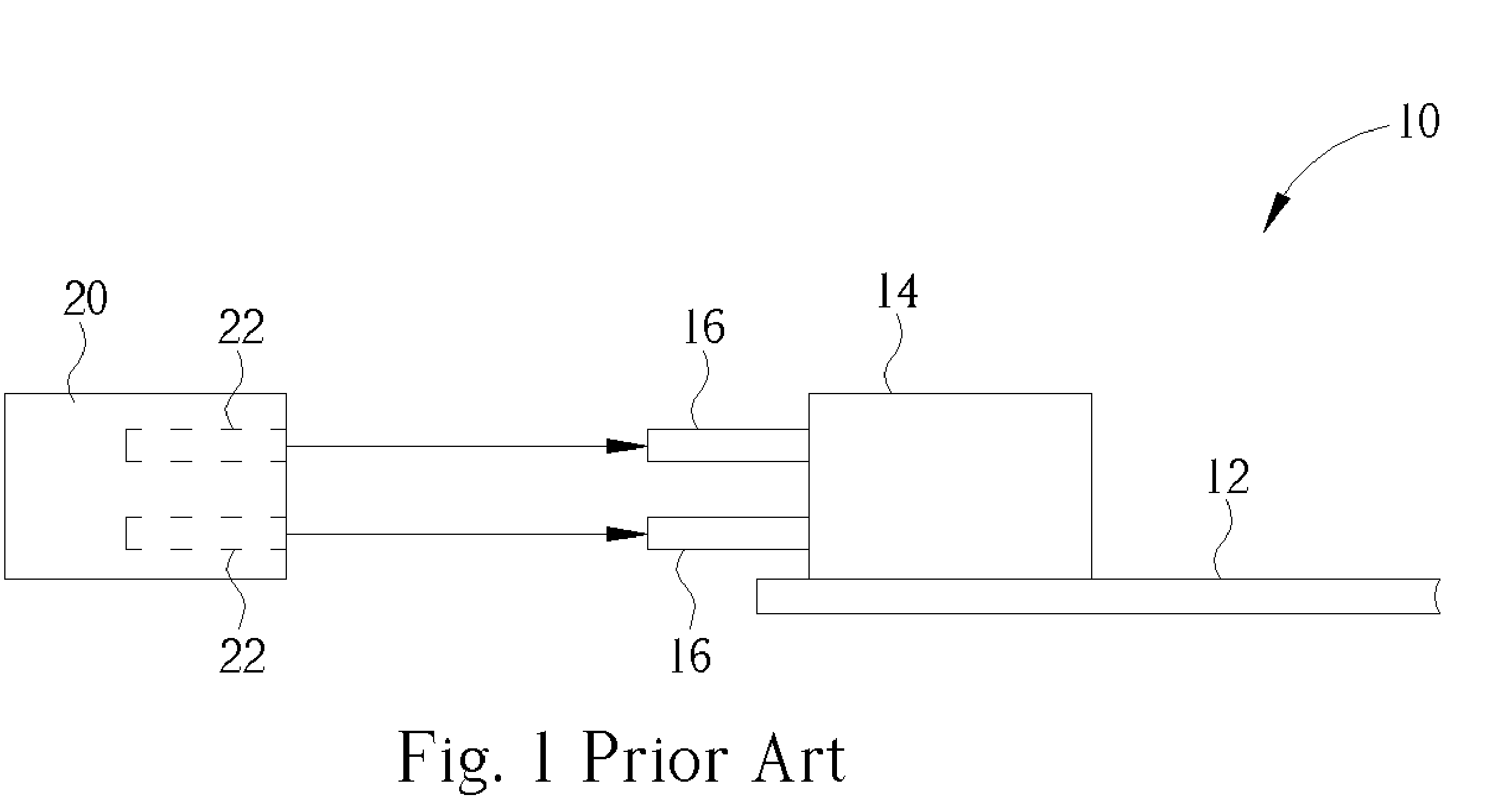
a detachable connection and printer technology, applied in the field of printers, can solve the problems of inconvenient disassembly and snapping of the conductor terminals b>16/b>, and achieve the effect of reducing the number of users and reducing the number of parts
- Summary
- Abstract
- Description
- Claims
- Application Information
AI Technical Summary
Benefits of technology
Problems solved by technology
Method used
Image

Examples
Embodiment Construction
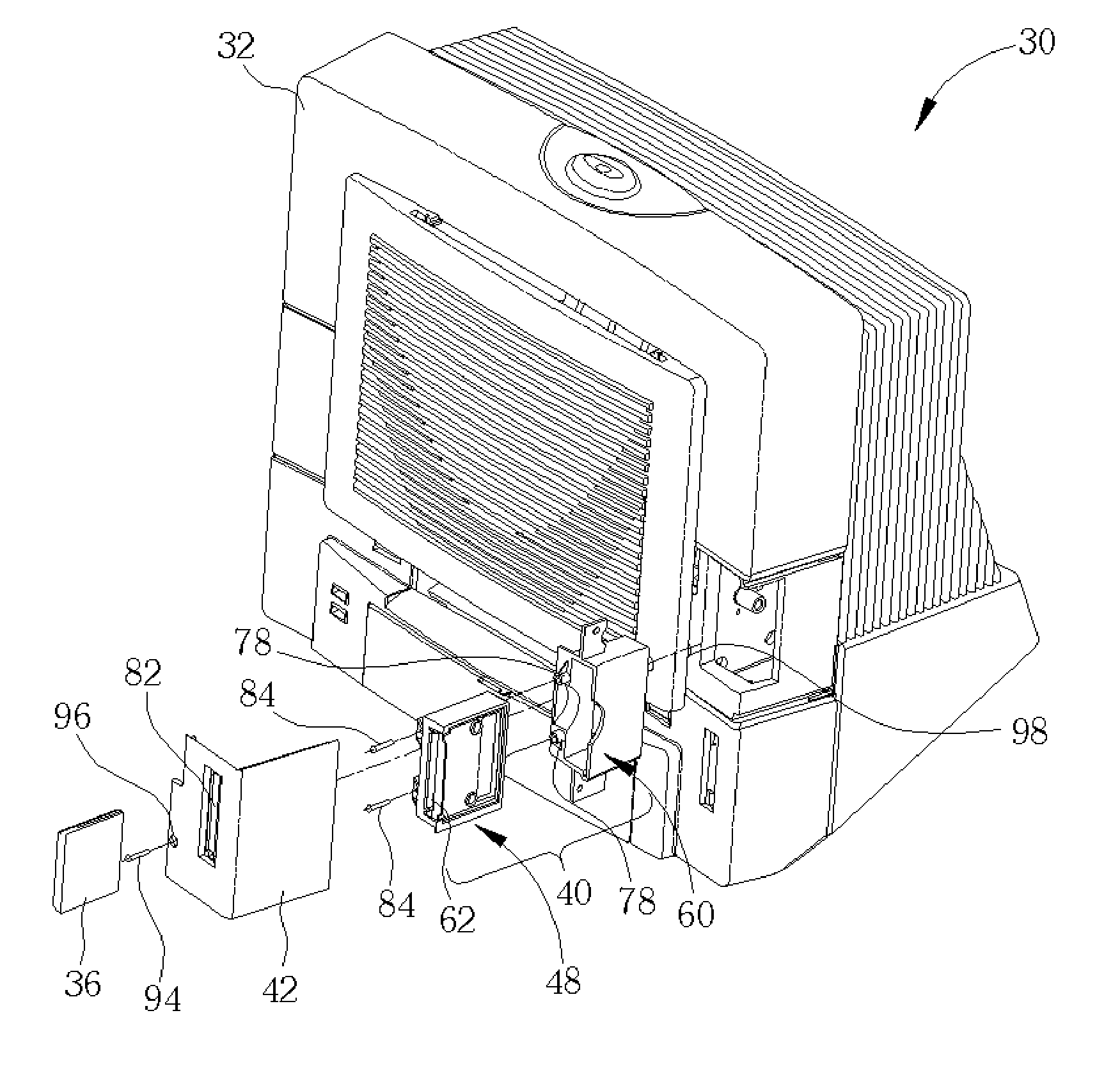
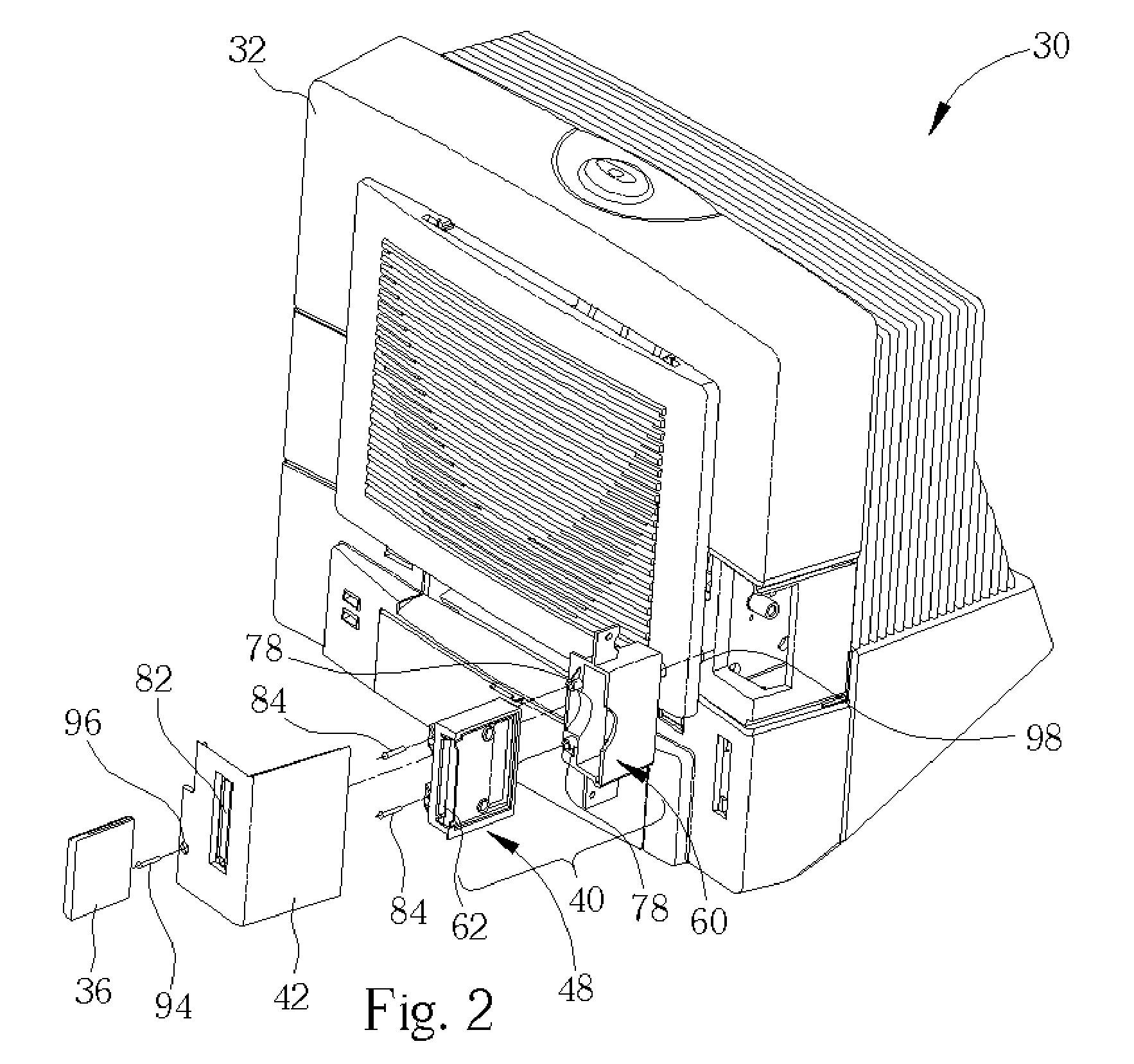
[0015]Please refer to FIGS. 2 and 3. FIG. 2 is an external view of a photo printer according to the present invention. FIG. 3 is an internal schematic diagram of the photo printer 30 depicted in FIG. 2. The printer 30 comprises a housing 32, a circuit board 12 (not shown), a dust-preventive member 42, a connection module 40, and an external card 36. The circuit board 12 installed within the housing 32, comprises a first set of female conducting terminals 56 and a controller (not shown) for controlling the operation of the printer 30. The connection module 40 comprises an adapter 48 and a shell 60. The adapter 48 comprises a first set of male conducting terminals 50 for connecting with the first set of female conducting terminals 56 and a second set of male conducting terminals 52. The shell 60 is used for accommodating the adapter 48. The external card 36, such as a compact flash card or other familiar memory card, is used for storing data. The external card 36 comprises a second se...
PUM
 Abstract
Description
Claims
Application Information