Photo printer

a technology of photo printers and printers, applied in the field of photo printers, can solve the problems of troublesome printing operation and complex structure, and achieve the effect of simplifying the size of the full color image printing apparatus and reducing the siz

a technology of photo printers and printers, applied in the field of photo printers, can solve the problems of troublesome printing operation and complex structure, and achieve the effect of simplifying the size of the full color image printing apparatus and reducing the siz

US7030897B2Inactive Publication Date: 2006-04-18FUNAI ELECTRIC CO LTD

Image

  • Photo printer
  • Photo printer
  • Photo printer

Examples


Embodiment Construction

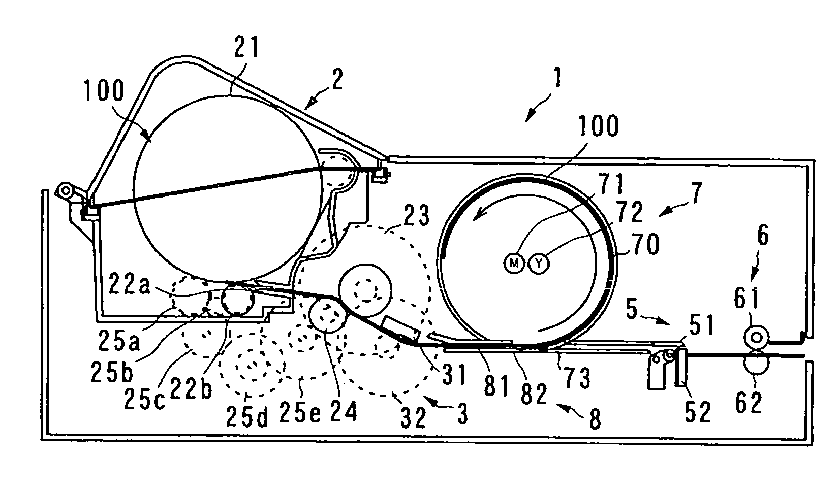
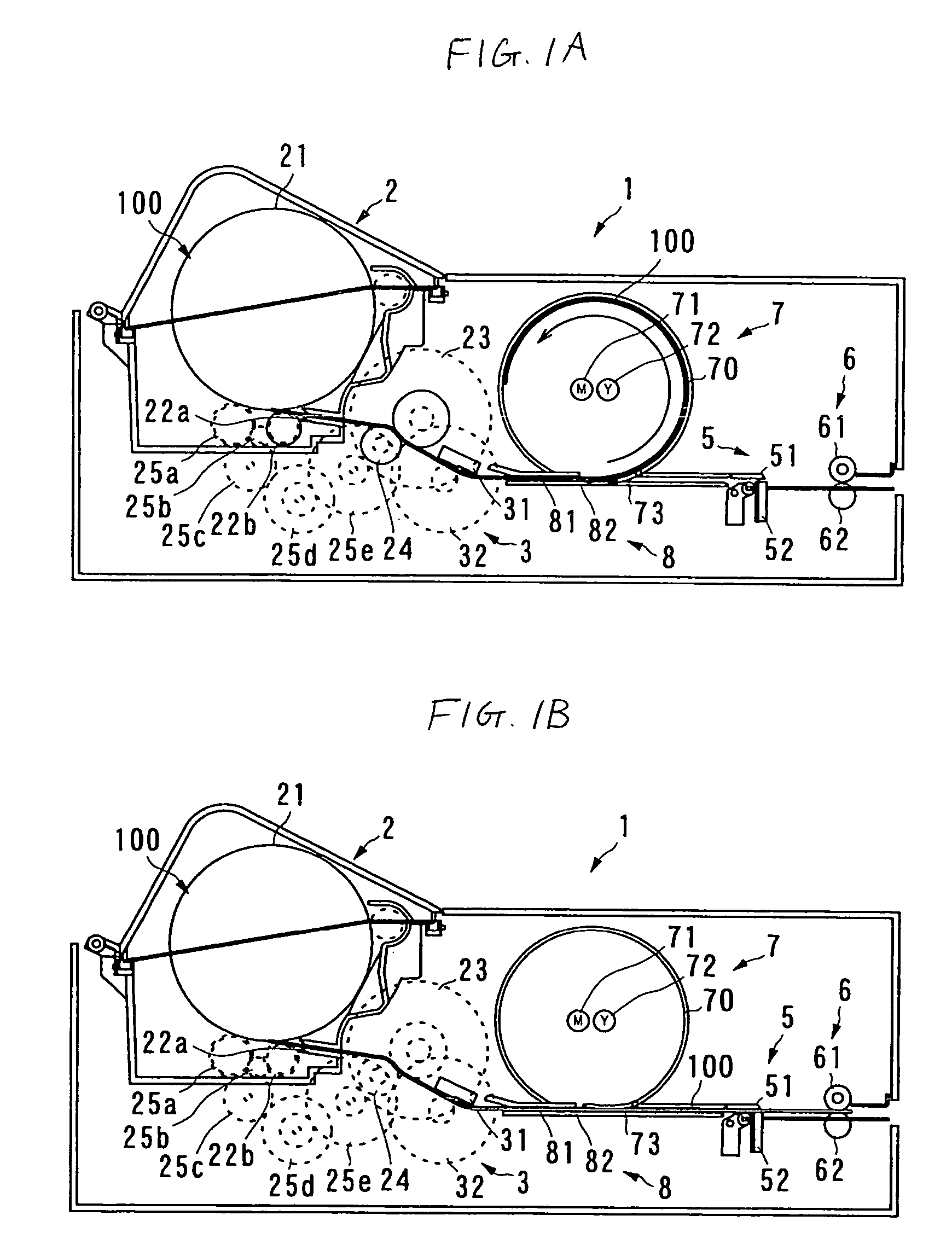
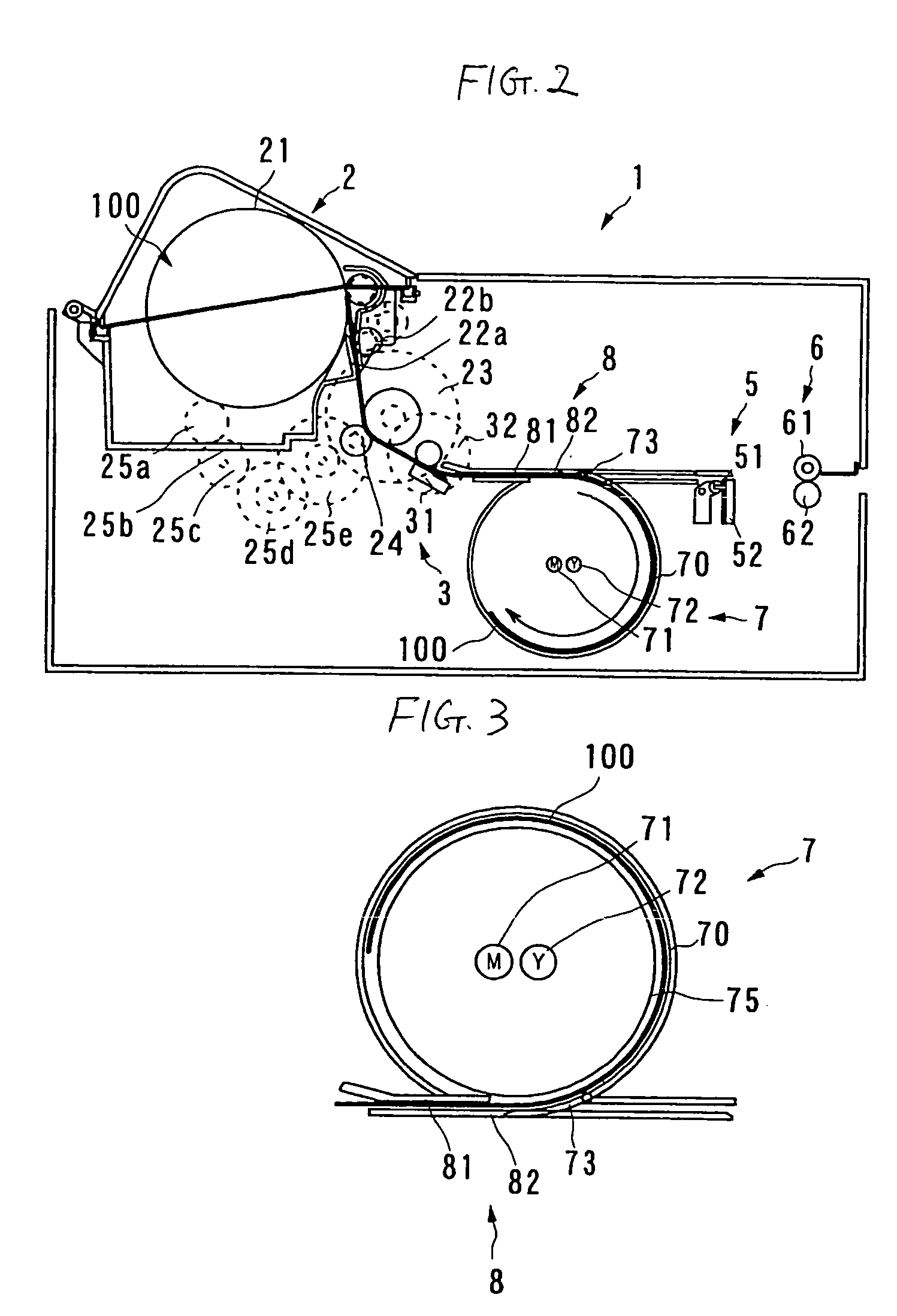
[0033]A photo printer according to an embodiment of the present invention will be described below with reference to the accompanying drawings. In the following explanation, the photo printer of a TA method (thermo auto-chrome method or direct photosensitive recording method of light fixation type) is taken as an example. Herein, the TA method involves forming a full-color image by repeating the image formation by heating and the image fixation by ultraviolet radiation on a TA paper which has a laminate of three thermal coloring layers that are colored in three primary colors of yellow (Y), magenta (M) and cyan (C).

[0034]FIG. 1 is a schematic view showing a principal portion of the photo printer of the invention. FIG. 1A shows a case where a roll paper 100 is inserted into a drum 7 of an image fixing portion 7 and FIG. 1B shows a case where the roll paper 100 is forwarded in a direction to a delivery portion 6,

[0035]As shown in FIG. 1, the photo printer 1 of this embodiment includes ...


PUM


Abstract

An image fixing portion includes a drum of cylindrical shape provided on a conveyance passage, a magenta fluorescent lamp and a yellow fluorescent lamp installed near the axis of the drum, and a fixing portion guide guiding the roll paper to be conveyed along the inner wall of the drum on the conveyance passage. The magenta fluorescent lamp and the yellow fluorescent lamp are disposed so that their axial direction may be coincident to the axial direction of the drum. When the image fixation is made, the roll paper is led into the drum. The roll paper has its image forming area alone led into the inside of the drum, so that light from each fluorescent lamp is applied to the image forming area alone.

Description

BACKGROUND OF THE INVENTION[0001]1. Field of the Invention[0002]The present invention relates to a photo printer for forming an image on a roll paper by heating, and then fixing the image by applying a light having a predetermined wavelength.[0003]2. Description of the Related Art[0004]The photo printer forms a full color image by repeating a process of image formation by heating of a thermal head and image fixation by applying ultraviolet radiation, using a roll paper having a laminate of three thermally coloring layers that are colored in three primary colors of Y (yellow), M (magenta) and C (cyan).[0005]Referring to FIG. 5, an image forming and fixing process for the conventional photo printer will be described below. FIG. 5 is a schematic view showing successively an image forming and fixing process for the conventional photo printer. Reference numeral 3 denotes an image forming portion, 4 denotes an image fixing portion, 23, 24 denote a pair of conveying rollers for conveying a...

Claims


Application Information

Patent Timeline
18 Apr 2006
Publication
US7030897B2
IPC
B41J29/377; B41J15/04; B41J2/32; B41J2/325; B41J11/00
CPC
B41J2/32; B41J11/002; B41J2202/34; B41J11/00214; B41J11/00218
Inventors
MATSUKAWA, CHIHARU