Imaging lens

a technology of imaging and lens, which is applied in the field of imaging lenses, can solve the problems of inability to reduce the effective diameter of the third lens, inability to produce compact lenses, and inability to achieve compact lenses, etc., and achieves the effects of convenient implementation of invention, high degree of reliability, and convenient image obtaining

Inactive Publication Date: 2006-01-24
DO SATOSHI +1
View PDF18 Cites 10 Cited by
  • Summary
  • Abstract
  • Description
  • Claims
  • Application Information

AI Technical Summary

Benefits of technology

[0036]The conditional expression (1) illustrated above is a condition for determining the ratio r1 / r2 of the axial curvature radius r1 of the first surface of the first lens L1 and the axial curvature radius r2 of the second surface of the first lens L1. If the ratio r1 / r2 is larger than the lower limit provided by the conditional expression (1), then the back focus of the imaging lens is sufficient for inserting a component such as a cover glass or filter between the imaging lens and the imaging surface, and thus the back focus can be set within a range which does not impair the compactness of the device into which the imaging lens is to be installed. Moreover, distortion can be reduced sufficiently, and hence manufacturing of the first surface of the first lens L1 is facilitated.
[0048]Further, it is well known that cycloolefin plastic materials are suitable for forming lenses according to injection molding methods that are already well-established as manufacturing techniques. Moreover, cycloolefin plastic materials have a record of usage in other lens systems to the imaging lens of the present invention, and hence if a cycloolefin plastic material is used, an imaging lens with a high degree of reliability can be manufactured.

Problems solved by technology

Further, a diaphragm is disposed on the object-side surface of the first lens, and hence the effective diameter of the third lens cannot be reduced.
As a result, a compact lens cannot be produced.
Hence, although these imaging lenses are set with a short combined imaging lens focal length, the back focus is long, and thus the optical length is too long.
In addition, these lenses use glass materials, and are therefore expensive.
In addition, the lenses use glass materials, and are therefore expensive.
However, the refractive power of the three lenses in this imaging lens, which are arranged as first, second, and third lenses in succession from the object side, is weak in the first lens, weak in the second lens, and positive in the third lens, and hence the refractive power of the first lens and second lens cannot be fully compensated for by the third lens alone.
As a result, the back focus lengthens, causing an increase in the optical length.
Furthermore, the third lens uses a glass material, and hence cost reduction is incomplete.
This is unsuitable for installation in image input devices of portable telephones or personal computers, digital cameras, CCD cameras used for monitoring purposes, surveying devices, and so on.
In this lens system, however, the back focus is short in relation to the focal length, and hence it is difficult to insert components such as a filter between the imaging lens and imaging surface.
Since components such as a filter must be inserted between the imaging lens and imaging surface in image input devices of portable telephones and the like, this lens is difficult to use in such an application.

Method used


Image

  • Imaging lens
  • Imaging lens
  • Imaging lens

Examples


first embodiment

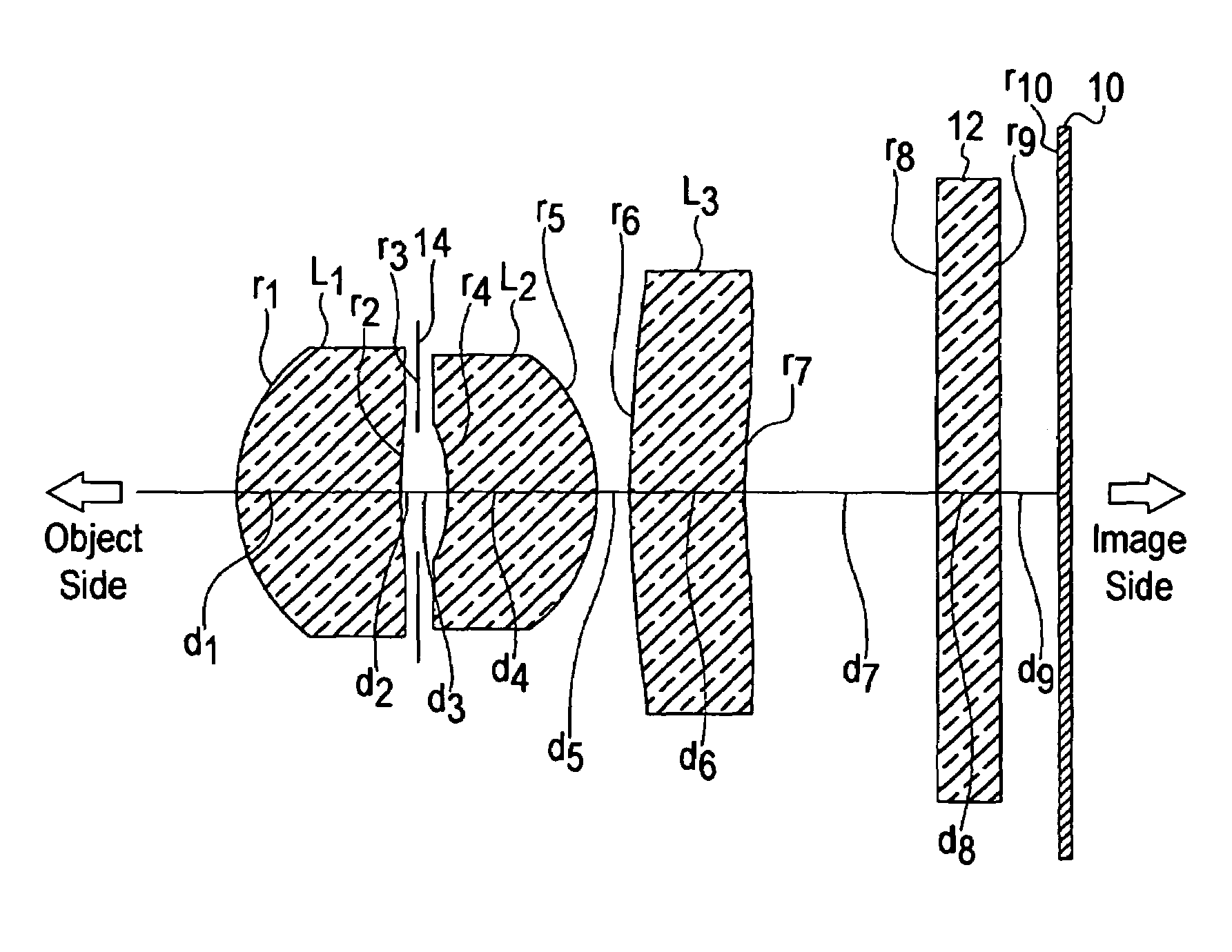
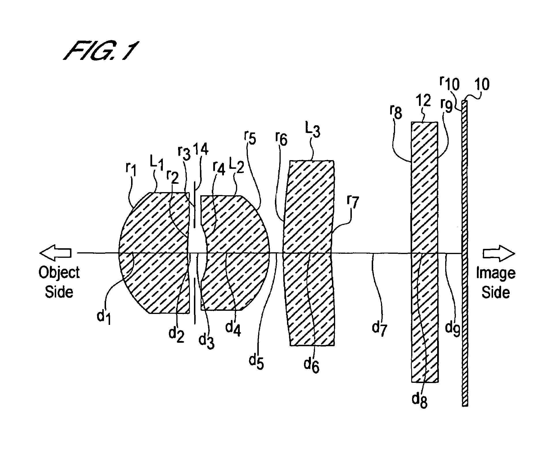
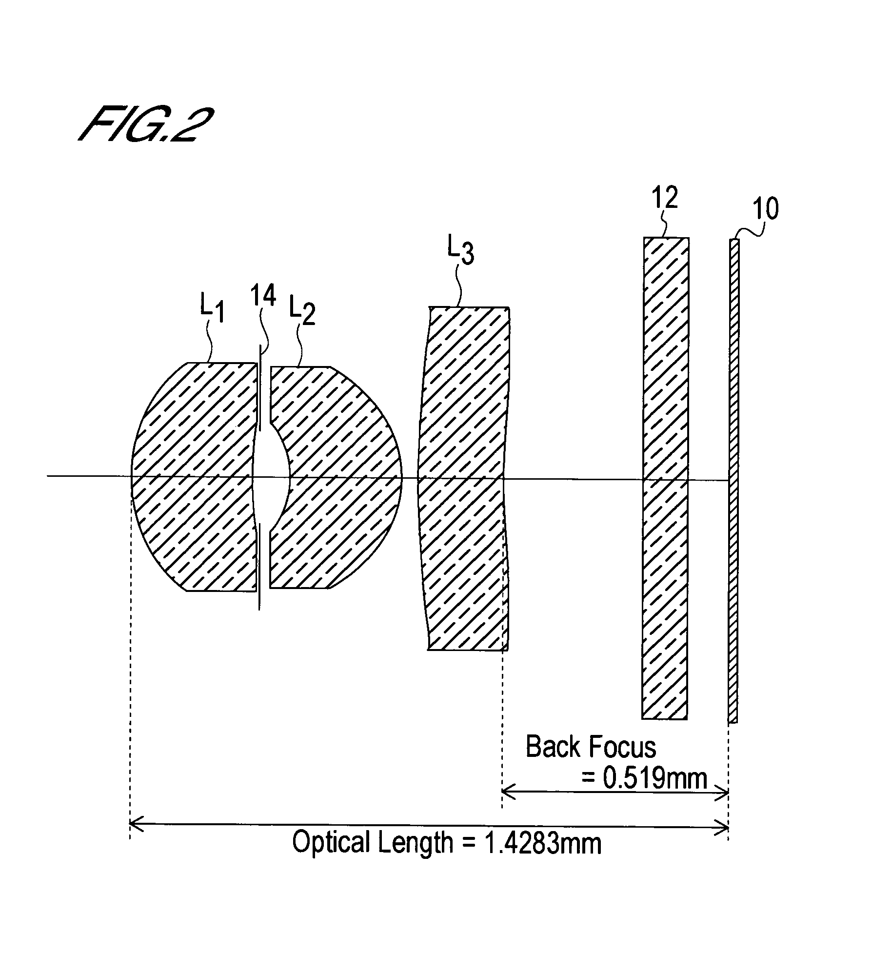
[0101](A) The object-side curvature radius r1 of the first lens L1 is r1=0.391 mm.[0102](B) The image-side curvature radius r2 of the first lens L1 is r2=0.806 mm.[0103](C) The back focus bf is bf=0.519 mm.[0104](D) The distance in air from the object-side surface of the first lens L1 to the imaging surface, or in other words the optical length d, is d=1.4283 mm.[0105](E) The interval D2 between the first lens L1 and second lens L2 is D2=d2+d3=0.0899 mm.[0106](F) The thickness D3 at the center of the second lens L2 is D3=d4=0.2745 mm.[0107](G) The focal length f1 of the first lens L1 is f1=1.16 mm.[0108](H) The focal length f2 of the second lens L2 is f2=1.16 mm.[0109](I) The focal length f3 of the third lens L3 is f3=−3.7 mm.[0110]Hence[0111](1) r1 / r2=0.391 / 0.806=0.4851[0112](2) D2 / f=0.0899 / 1.00=0.0899[0113](3) D3 / f=0.2745 / 1.00=0.2745[0114](4) d / f=1.4283 / 1.00=1.4283, and[0115](5) bf / f=0.519 / 1.00=0.519.

[0116]Thus the lens system of the first embodiment satisfies all of the following...

second embodiment

[0125](A) The object-side curvature radius r1 of the first lens L1 is r1=0.351 mm.[0126](B) The image-side curvature radius r2 of the first lens L1 is r2=0.608 mm.[0127](C) The back focus bf is bf=0.470 mm.[0128](D) The distance in air from the object-side surface of the first lens L1 to the imaging surface, or in other words the optical length d, is d=1.3714 mm.[0129](E) The interval D2 between the first lens L1 and second lens L2 is D2=d2+d3=0.0906 mm.[0130](F) The thickness D3 at the center of the second lens L2 is D3=d4=0.2768 mm.[0131](G) The focal length f1 of the first lens L1 is f1=1.13 mm.[0132](H) The focal length f2 of the second lens L2 is f2=1.19 mm.[0133](I) The focal length f3 of the third lens L3 is f3=−3.77 mm.[0134]Hence[0135](1) r1 / r2=0.351 / 0.608=0.5773[0136](2) D2 / f=0.0906 / 1.00=0.0906[0137](3) D3 / f=0.2768 / 1.00=0.2768[0138](4) d / f=1.3714 / 1.00=1.3714, and[0139](5) bf / f=0.470 / 1.00=0.47.

[0140]Thus the lens system of the second embodiment satisfies the conditional exp...

third embodiment

[0148](A) The object-side curvature radius r1 of the first lens L1 is r1=0.353 mm.[0149](B) The image-side curvature radius r2 of the first lens L1 is r2=0.611 mm.[0150](C) The back focus bf is bf=0.454 mm.[0151](D) The distance in air from the object-side surface of the first lens L1 to the imaging surface, or in other words the optical length d, is d=1.3746 mm.[0152](E) The interval D2 between the first lens L1 and second lens L2 is D2=d2+d3=0.0909 mm.[0153](F) The thickness D3 at the center of the second lens L2 is D3=d4=0.278 mm.[0154](G) The focal length f1 of the first lens L1 is f1=1.14 mm.[0155](H) The focal length f2 of the second lens L2 is f2=1.19 mm.[0156](I) The focal length f3 of the third lens L3 is f3=−3.79 mm.[0157]Hence[0158](1) r1 / r2=0.353 / 0.611=0.5778[0159](2) D2 / f=0.0909 / 1.00=0.0909[0160](3) D3 / f=0.278 / 1.00=0.278[0161](4) d / f=1.3746 / 1.00=1.3746, and[0162](5) bf / f=0.454 / 1.00=0.454.

[0163]Thus the lens system of the third embodiment satisfies the conditional expres...


PUM


Abstract

The present invention is an imaging lens in which various aberrations are satisfactorily corrected, the optical length is short, and a sufficient back focus is secured. The imaging lens is constituted by arranging a first lens L1, an aperture diaphragm S1, a second lens L2, and a third lens L3 in succession from the object side to the image side.

Description

BACKGROUND OF THE INVENTION[0001]1. Field of the Invention[0002]The present invention relates to an imaging lens, and more particularly to an imaging lens which is suitable for installation into an image input device of a portable telephone or personal computer, a digital camera, a CCD camera used for monitoring purposes, a surveying device, or similar which uses a CCD or CMOS as an imaging device.[0003]2. Description of Related Art[0004]In such an imaging lens, the optical length, which is defined as the distance from the entrance surface on the object side of the imaging lens to the imaging surface (the image-forming surface of a CCD or the like), must be short. In other words, during design of the lens, a method of reducing the ratio of the optical length to the combined focal length of the imaging lens is required. An imaging lens having a short optical length and a small optical length to focal length ratio will occasionally be referred to as a compact lens below.[0005]Taking a...

Claims


Application Information

Patent Timeline
Patent Type & Authority Patents(United States)
IPC IPC(8): G02B9/12G02B13/00G02B13/16G02B13/18
CPCG02B13/0035G02B9/12G02B13/18G02B1/041G03B9/02
Inventor DO
Owner DO SATOSHI
Why Eureka
Try Eureka