Imaging lens

a technology of imaging lens and optical length, which is applied in the field of imaging lens, can solve the problems of inability to reduce the effective diameter of the third lens, inability to produce compact lenses, etc., and achieve the effect of high degree of reliability

Inactive Publication Date: 2006-01-10
MILESTONE CO LTD +1
View PDF15 Cites 38 Cited by
  • Summary
  • Abstract
  • Description
  • Claims
  • Application Information

AI Technical Summary

Benefits of technology

[0032]The conditional expression (1) illustrated above is for determining the ratio r1 / r2 of the axial curvature radius r1 of the first surface of the first lens L1 and the axial curvature radius r2 of the second surface of the first lens L1. If the ratio r1 / r2 is larger than the lower limit provided by the conditional expression (1), then the back focus of the imaging lens is sufficient for inserting a component such as a cover glass or filter between the imaging lens and the image surface, and thus the back focus can be set within a range which does not impair the compactness of the device into which the imaging lens is to be installed. Moreover, distortion can be reduced sufficiently, and hence manufacturing of the first surface of the first lens L1 is facilitated.
[0043]Further, it is well known that cycloolefin plastic materials are suitable for forming lenses according to injection molding methods. Injection molding methods are already well-established as manufacturing techniques in the formation of lenses. Moreover, cycloolefin plastic materials have a record of usage in other lens systems than the imaging lens of the present invention, and hence if a cycloolefin plastic material is used, an imaging lens with a high degree of reliability can be manufactured.

Problems solved by technology

Further, in this imaging lens, a diaphragm is disposed on the object side surface of the first lens, and hence the effective diameter of the third lens cannot be reduced.
As a result, a compact lens cannot be produced.
Hence, although these imaging lenses are set with a short combined focal length as an imaging lens, the back focus is long, and thus the optical length is too long.
In addition, these imaging lenses use glass materials, and are therefore expensive.
In addition, the lenses of the imaging lens use glass materials, and are therefore expensive.
Hence the refractive power of the first lens and second lens in this imaging lens cannot be fully compensated for by the third lens alone.
As a result, the back focus lengthens, causing an increase in the optical length.
Furthermore, the third lens of this imaging lens uses a glass material, and hence cost reduction is incomplete.
This is unsuitable for installation in image input devices of portable telephones or personal computers, digital cameras, CCD cameras used for monitoring purposes, surveying devices, and so on.

Method used


Image

  • Imaging lens
  • Imaging lens
  • Imaging lens

Examples


first embodiment

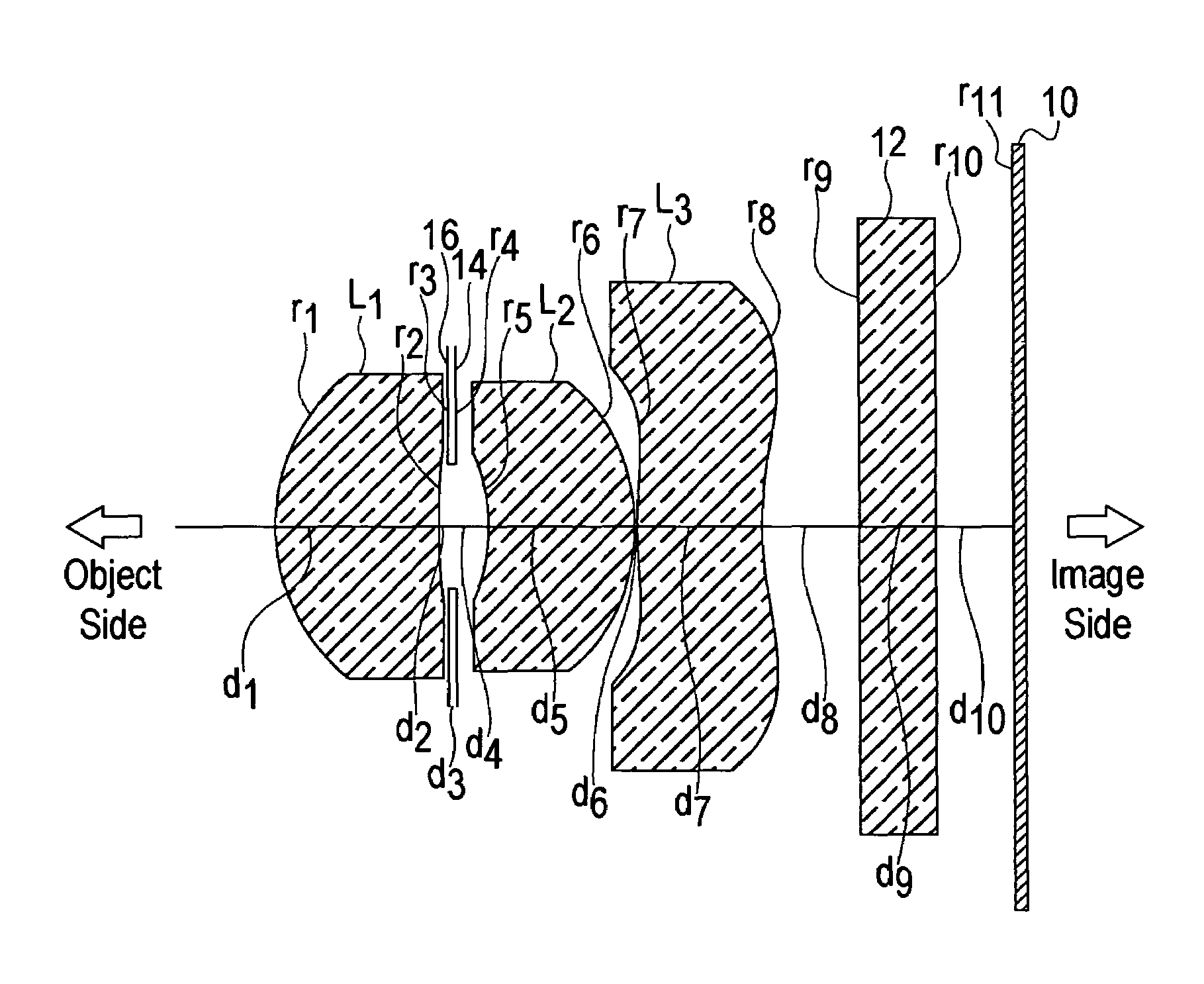
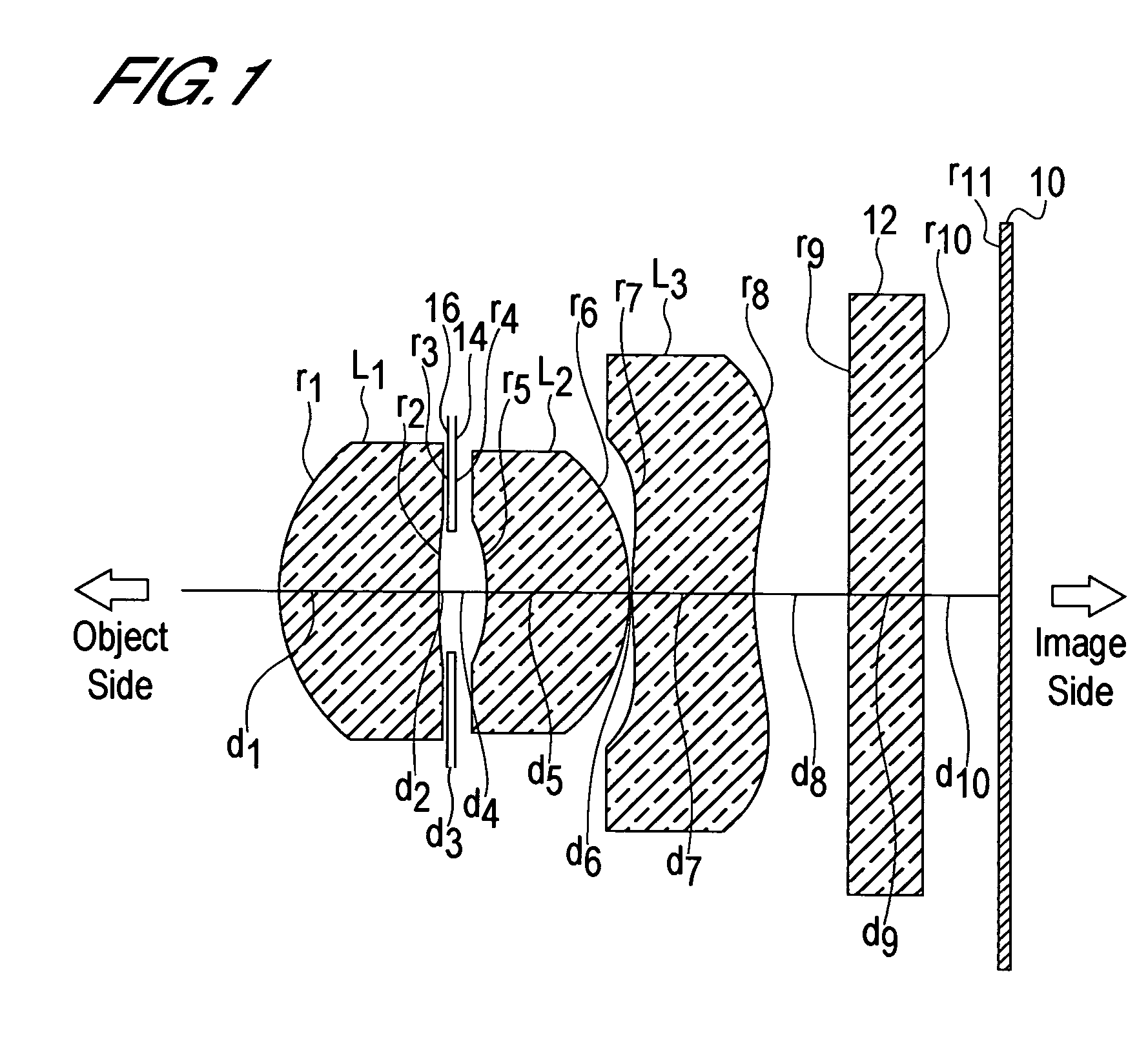
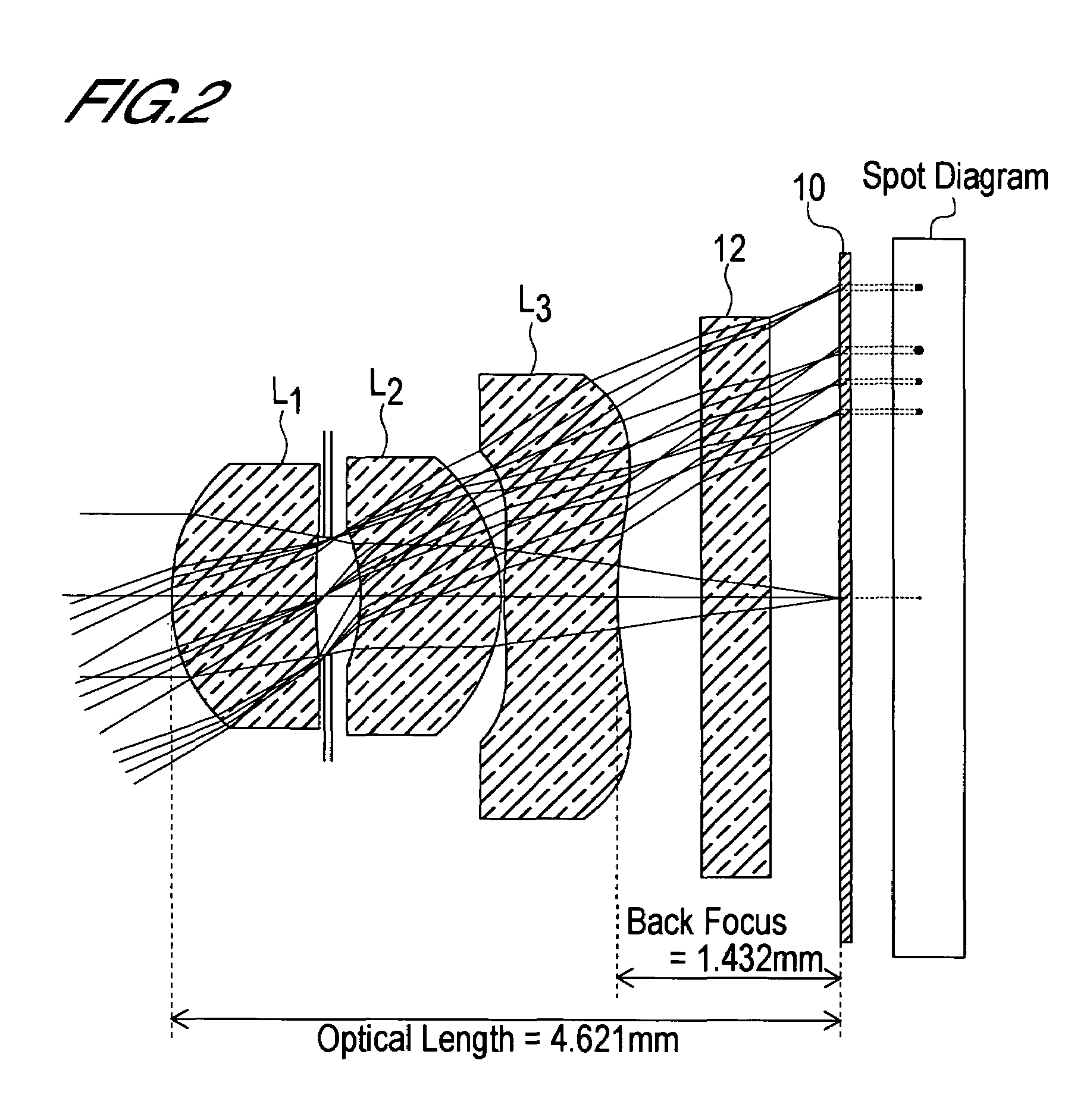
[0097[0098](A) The focal length f of the entire lens system is f=3.656 mm.[0099](B) The object side curvature radius r1 of the first lens L1 is r1=1.34 mm.[0100](C) The image side curvature radius r2 of the first lens L1 is r2=4.61 mm.[0101](D) The back focus bf is bf=1.432 mm.[0102](E) The distance in air from the object side surface of the first lens L1 to the image surface, or in other words the optical length d, is d=4.621 mm.[0103](F) The distance D2 between the first lens L1 and second lens L2 is D2=0.32 mm.[0104](G) The thickness D3 at the center of the second lens L2 is D3=d5=1.00 mm.[0105](H) The focal length f1 of the first lens L1 is f1=3.24 mm.[0106](I) The focal length f2 of the second lens L2 is f2=25.67 mm.[0107](J) The focal length f3 of the third lens L3 is f3=−24.15 mm.

[0108]Hence

r1 / r2=1.34 / 4.61=0.2907  (1)

D2 / f=0.32 / 3.656=0.0875  (2)

D3 / f=1.00 / 3.656=0.2735, and  (3)

d / f=4.621 / 3.656=1.2639.  (4)

[0109]Thus the lens system of the first embodiment satisfies all of the fo...

second embodiment

[0119[0120](A) The focal length f of the entire lens system is f=3.697 mm.[0121](B) The object side curvature radius r1 of the first lens L1 is r1=1.36 mm.[0122](C) The image side curvature radius r2 of the first lens L1 is r2=4.68 mm.[0123](D) The back focus bf is bf=1.457 mm.[0124](E) The distance in air from the object side surface of the first lens L1 to the image surface, or in other words the optical length d, is d=4.627 mm.[0125](F) The distance D2 between the first lens L1 and second lens L2 is D2=0.32 mm.[0126](G) The thickness D3 at the center of the second lens L2 is D3=d5=0.95 mm.[0127](H) The focal length f1 of the first lens L1 is f1=3.29 mm.[0128](I) The focal length f2 of the second lens L2 is f2=29.7 mm.[0129](J) The focal length f3 of the third lens L3 is f3=−24.12 mm.

[0130]Hence

r1 / r2=1.36 / 4.68=0.2906  (1)

D2 / f=0.32 / 3.697=0.0866  (2)

D3 / f=0.95 / 3.697=0.257, and  (3)

d / f=4.627 / 3.697=1.2516.  (4)

[0131]Thus the lens system of the second embodiment satisfies all of the fol...

third embodiment

[0140[0141](A) The focal length f of the entire lens system is f=5.428 mm.[0142](B) The object side curvature radius r1 of the first lens L1 is r1=2.00 mm.[0143](C) The image side curvature radius r2 of the first lens L1 is r2=6.92 mm.[0144](D) The back focus bf is bf=2.099 mm.[0145](E) The distance in air from the object side surface of the first lens L1 to the image surface, or in other words the optical length d, is d=6.859 mm.[0146](F) The distance D2 between the first lens L1 and second lens L2 is D2=0.48 mm.[0147](G) The thickness D3 at the center of the second lens L2 is D3=d5=1.47 mm.[0148](H) The focal length f1 of the first lens L1 is f1=4.82 mm.[0149](I) The focal length f2 of the second lens L2 is f2=39.15 mm.[0150](J) The focal length f3 of the third lens L3 is f3=−36.15 mm.

[0151]Hence

r1 / r2=2.00 / 6.92=0.289  (1)

D2 / f=0.48 / 5.428=0.0884  (2)

D3 / f=1.47 / 5.428=0.2708, and  (3)

d / f=6.859 / 5.428=1.2636.  (4)

[0152]Thus the lens system of the third embodiment satisfies all of the fol...


PUM


Abstract

In an imaging lens of the present invention, aberration is satisfactorily corrected, the optical length is short, and sufficient back focus is secured. The imaging lens of the present invention is constituted by arranging a first lens L1, an aperture diaphragm S1, a second lens L2, and a third lens L3 in succession from the object side to the image side.

Description

BACKGROUND OF THE INVENTION[0001]1. Field of the Invention[0002]The present invention relates to an imaging lens, and more particularly to an imaging lens which is suitable for installation into an image input device of a portable telephone or personal computer, a digital camera, a CCD camera used for monitoring purposes, a surveying device, or similar which uses a CCD or CMOS as an imaging device.[0003]2. Description of Related Art[0004]In such an imaging lens, the optical length, which is defined as the distance from the entrance surface on the object side of the imaging lens to the image surface (the image-forming surface of a CCD or the like), must be short. An imaging lens having a short optical length will occasionally be referred to as a compact lens below.[0005]Taking a portable telephone as an example, the optical length must at least be shorter than the thickness of the portable telephone body. Meanwhile, the back focus, which is defined as the distance from the exit surfa...

Claims


Application Information

Patent Timeline
Patent Type & Authority Patents(United States)
IPC IPC(8): G02B13/18G02B9/12G02B9/34G02B13/00
CPCG02B13/0035G02B9/12G02B13/18G02B1/041
Inventor DO, SATOSHI
Owner MILESTONE CO LTD
Why Eureka
Try Eureka