Radio frequency local area network

a local area network and radio frequency technology, applied in data switching networks, instruments, polarised antenna unit combinations, etc., can solve the problems of difficulty in maintaining the integrity of such multiple-hop rf data communication systems, and difficulty in maintaining the integrity of wireless communications, so as to achieve efficient and dynamic data handling

Inactive Publication Date: 2006-01-24
AVAGO TECH INT SALES PTE LTD
View PDF4 Cites 33 Cited by
  • Summary
  • Abstract
  • Description
  • Claims
  • Application Information

AI Technical Summary

Benefits of technology

[0018]The present invention solves many of the problems inherent in a multiple-hop data communication system. The present invention comprises an RF Local-Area Network capable of efficient and dynamic handling of data by routing communications between the RF Terminals and the host computer through a network of intermediate base stations.
[0019]In one embodiment of the present invention, the RF data communication system contains one or more host computers and multiple gateways, bridges, and RF terminals. Gateways are used to pass messages to and from a host computer and the RF Network. A host port is used to provide a link between the gateway and the host computer. In addition, gateways may include bridging functions and may pass information from one RF terminal to another. Bridges are intermediate relay nodes which repeat data messages. Bridges can repeat data to and from bridges, gateways and RF terminals and are used to extend the range of the gateways.
[0022]One object of the present invention is to route data efficiently, dynamically, and without looping. Another object of the present invention is to make the routing of the data transparent to the RF terminals. The RF terminals, transmitting data intended for the host computer, are unaffected by the means ultimately used by the RF Network to deliver their data.

Problems solved by technology

Difficulties often arise in maintaining the integrity of such multiple-hop RF data communication systems.
In such wireless networks, difficulties often arise in maintaining the integrity of wireless communications.

Method used


Image

  • Radio frequency local area network
  • Radio frequency local area network
  • Radio frequency local area network

Examples


Embodiment Construction

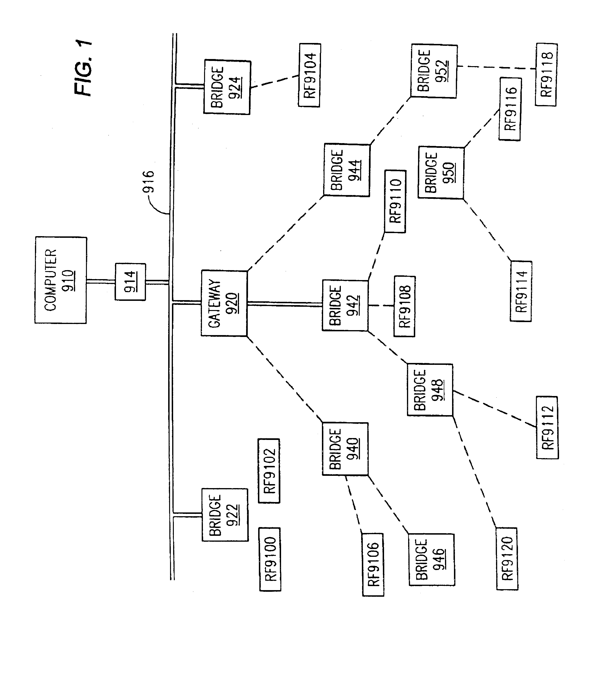
[0038]FIG. 1 is a functional block diagram of an RF data communication system. In one embodiment of the present invention, the RF data communication system has a host computer 910, a network controller 914 and bridges 922 and 924 attached to a data communication link 916. Also attached to the data communication link 916 is a gateway 920 which acts as the root node for the spanning tree of the RF data network of the present invention. A bridge 942 is attached to the gateway 920 through a hard-wired communication link and bridges 940 and 944 are logically attached to gateway 920 by two independent RF links. Additional bridges 946, 948, 950 and 952 are also connected to the RF. Network and are shown in the FIG. 1. Note that, although shown separate from the host computer 910, the gateway 920 (the spanning tree root node) may be part of host computer 910.

[0039]FIG. 1 further shows RF terminals 9100 and 9102 attached to bridge 922 via RF links and RF terminal 9104 attached to bridge 924 ...


PUM


Abstract

An apparatus and a method for routing data in a radio data communication system having one or more host computers, one or more intermediate base stations, and one or more RF terminals organizes the intermediate base stations into an optimal spanning-tree network to control the routing of data to and from the RF terminals and the host computer efficiently and dynamically. Communication between the host computer and the RF terminals is achieved by using the network of intermediate base stations to transmit the data.

Description

CROSS REFERENCE TO RELATED APPLICATIONS[0001]The present application is a continuation of application Ser. No. 09 / 531,880, filed Mar. 21, 2000, now U.S. Pat. No. 6,400,702, issued Jun. 4, 2002; which is a continuation of application Ser. No. 09 / 089,950, filed Jun. 3, 1998, now U.S. Pat. No. 6,084,867, issued Jul. 4, 2000; which is a continuation of application Ser. No. 08 / 494,909, filed Jun. 26, 1995, now abandoned; which is a continuation-in-part of application Ser. No. 08 / 059,447, filed May 7, 1993, now U.S. Pat. No. 5,428,636, issued Jun. 27, 1995; which is a continuation-in-part of application Ser. No. 08 / 056,827, filed May 3, 1993, now U.S. Pat. No. 5,295,154, issued Mar. 15, 1994; which itself is a continuation of the application Ser. No. 07 / 769,425, filed Oct. 1, 1991, now abandoned. Said application Ser. No. 08 / 494,909 is also a continuation-in-part of application Ser. No. 08 / 318,154, filed Oct. 4, 1994, now abandoned; which is a continuation-in-part of application Ser. No. ...

Claims


Application Information

Patent Timeline
Patent Type & Authority Patents(United States)
IPC IPC(8): H04J15/00G06F1/16G06F15/02H01Q1/00H01Q1/22H01Q1/24H01Q21/24H04B1/16H04B1/38H04J99/00H04L1/00H04L12/12H04L12/28H04L12/46H04L12/56H04L29/06H04L29/08H04M1/73H04W8/26H04W40/02H04W40/22H04W40/24H04W40/28H04W40/30H04W40/36H04W84/04H04W84/12H04W88/06H04W88/08H04W88/14H04W92/20
CPCG06F15/0225H01Q1/007H01Q1/241H01Q21/24H04B1/3833H04L1/0025H04L12/12H04L12/462H04L29/06H04L45/00H04L45/04H04L45/44H04L45/48H04L47/6225H04L49/90H04L49/9057H04W40/02H04W88/06H04W88/14G06K7/1098H04L69/326H04L1/1607H04L1/1867H04W8/26H04W40/22H04W40/246H04W40/28H04W40/30H04W40/36H04W84/04H04W84/12H04W88/08H04W92/20H04L69/14H04L69/32H04L69/324H04L69/325H04L9/40H04L69/323
Inventor MEIER, ROBERT C.
Owner AVAGO TECH INT SALES PTE LTD
Why Eureka
Try Eureka