Multi-chute gravity feed dispenser display

Active Publication Date: 2006-01-31
GAMON PLUS
View PDF48 Cites 108 Cited by
  • Summary
  • Abstract
  • Description
  • Claims
  • Application Information

AI Technical Summary

Benefits of technology

[0046]FIG. 15 shows a plurality of multi-chute gravity feed dispenser displays disposed on a num

Problems solved by technology

One disadvantage of prior art gravity feed dispensers is that such devices are integrated into racks useful only for granting feed applications.
Prior art gravity feed dispensers are not designed to be used in connection with standard shelving already in place at the retailer.
Another disadvantage of prior art gravity feed dispensers is that they must be reloaded from the backside or topside thereof.
As a result, gravity feed dispensers are usually not disposed in a back-to-back orientation.
As a result, valuable floor space is wasted and the cost of operation i

Method used


Image

  • Multi-chute gravity feed dispenser display
  • Multi-chute gravity feed dispenser display
  • Multi-chute gravity feed dispenser display

Examples


Embodiment Construction

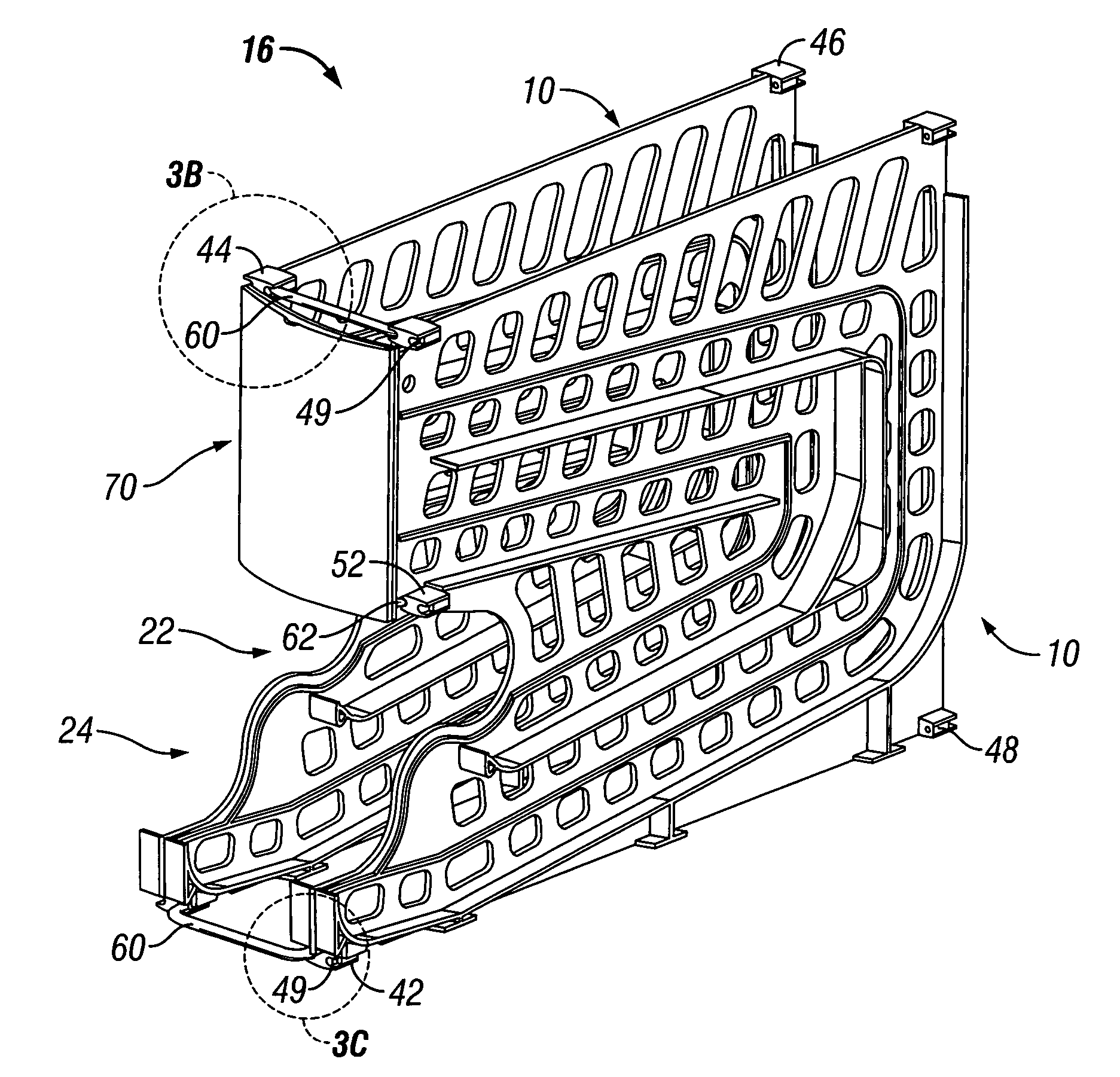
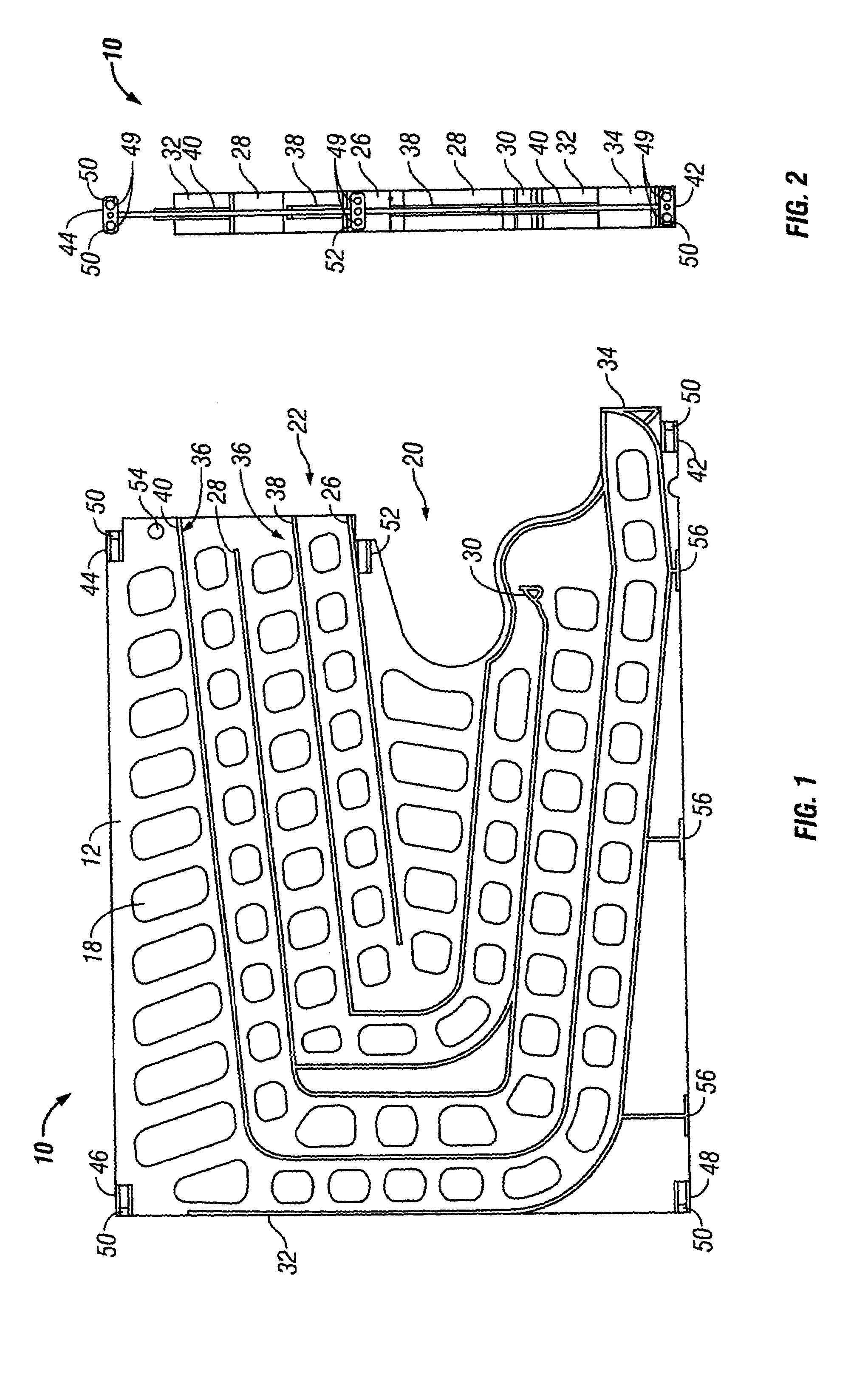
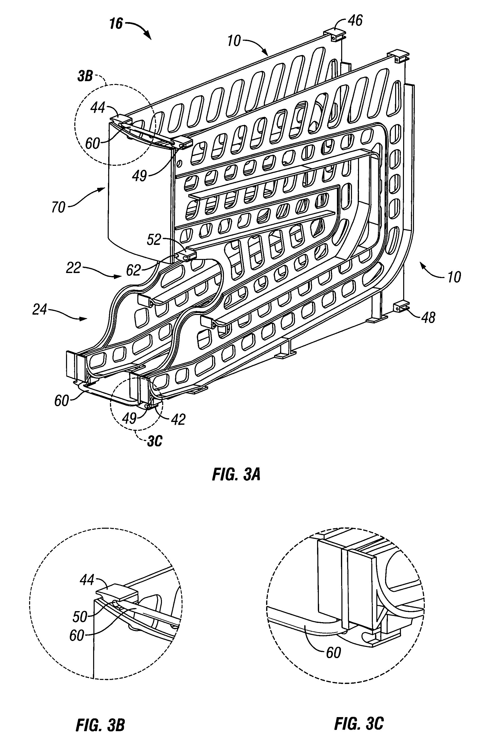
[0060]FIGS. 1 and 2 show a side and front view of the main element of the multi-chute gravity feed dispenser display, a panel 10 which is generally formed as a vertical upright panel. The panel 10 is preferably configured to be used in connection with conventional store shelving in place at a retailer having a depth in the range of 18 to 24 inches. In one embodiment of the invention the depth of the panel 10 is 20 inches overall and the height is 14 inches overall. It will be recognized by those of skill in the art that the embodiments discussed herein are configured to be adapted to conventional shelving. However, changes in scale or any dimension cited herein are within the scope of the present invention and may be adjusted based on any requirements for an application.

[0061]The panel 10 includes at least one set of rails 20 which are formed as ribs extending normal to a side 12 of the panel 10 to cooperatively define a plurality of chutes 22, 24 for product which have a boustrophe...


PUM


Abstract

A set of panels having chutes therebetween. The chutes being defined by curvilinear rails on such panels. The curvilinear rails having stops thereon for stopping the products for viewing.

Description

[0001]This application claims priority from provisional patent application No. 60 / 404,648, filed Aug. 20, 2002.BACKGROUND OF THE INVENTION[0002]1. Field of the Invention[0003]The present invention relates to dispenser racks and displays therefore, and more particularly, to a compact, easy to assemble, easy to load and unload multiple chute dispenser with an integrated display.[0004]2. Description of Related Art[0005]Gravity feed dispensers have been used in the product dispensing markets, i.e., grocery stores, supermarkets, convenience marts and department stores, to provide on shelf storage, automatic rotation of stock, easy access for customers. The principal of operation is quite simple. The products are arranged on a rack which is inclined to horizontal such that when a customer removes one product at an end of a row of products, the entire row of products indexes forward one location equivalent to one product. Rollers are known to ease movement of the product.[0006]One disadvan...

Claims


Application Information

Patent Timeline
IPC IPC(8): A47F7/00A47F1/08
CPCA47F1/087
Inventor JOHNSON, TERRY J.SCHOEMER, JOHNJOHNSON, TRAVIS O.
Owner GAMON PLUS
Why Eureka
Try Eureka