Capless automotive fueling system

a fueling system and capless technology, applied in the field of capless automotive fueling systems, can solve the problems of limiting the amount of fuel vapor escape from the automotive fuel system, insufficient sealing between the fuel funnel and the gas cap, and not only an inconvenience for the vehicle operator, but a major warranty expense for the automotive vehicle manufacturer

Active Publication Date: 2006-02-07
MARTINREA IND INC
View PDF39 Cites 37 Cited by
  • Summary
  • Abstract
  • Description
  • Claims
  • Application Information

AI Technical Summary

Benefits of technology

[0018]In order to protect the fuel valve from environmental hazards which may result in leakage of fuel vapors from the fuel tank and through the funnel, the system of the present invention includes a shield which is movable between a first position and a second position. In its first position, the shield overlies, covers and protects the fuel valve from the environment. Conversely, in its second position, the shield is moved laterally to one side of the valve to permit insertion of the fuel filling nozzle through the funnel port in the desired fashion.

Problems solved by technology

Such government regulations, furthermore, increasingly restrict the amount of fuel vapor escape from the automotive fuel system over time.
However, the failure of the vehicle operator to secure the gas cap onto the fuel filling funnel with sufficient torque will cause insufficient sealing between the fuel funnel and the gas cap.
When such a warning light is illuminated for the vehicle operator, the vehicle operator oftentimes returns the vehicle to the vehicle dealer or other maintenance facility only to discover that the only vehicle “malfunction” is that the gas cap has been too loosely installed on the vehicle.
This presents not only an inconvenience for the vehicle operator, but a major warranty expense for the automotive vehicle manufacturer.
A still further disadvantage of the conventional fuel filling systems for automotive vehicles is that the flapper valve which closes the funnel port is freely movable between an open and a closed position.
Consequently, since the fuel nozzle for diesel fuel has a larger diameter than the fuel nozzle for unleaded gasoline, the fuel nozzle for diesel fuel cannot be inserted into the fuel funnel assembly for a vehicle which utilizes unleaded gasoline.
Unfortunately, the converse is not true.
This, in turn, results in damage if not destruction of the engine.
However, repeated flexing of the latches can result in weakening or even breakage of the latches thus rendering them inoperable.

Method used


Image

  • Capless automotive fueling system
  • Capless automotive fueling system
  • Capless automotive fueling system

Examples


Embodiment Construction

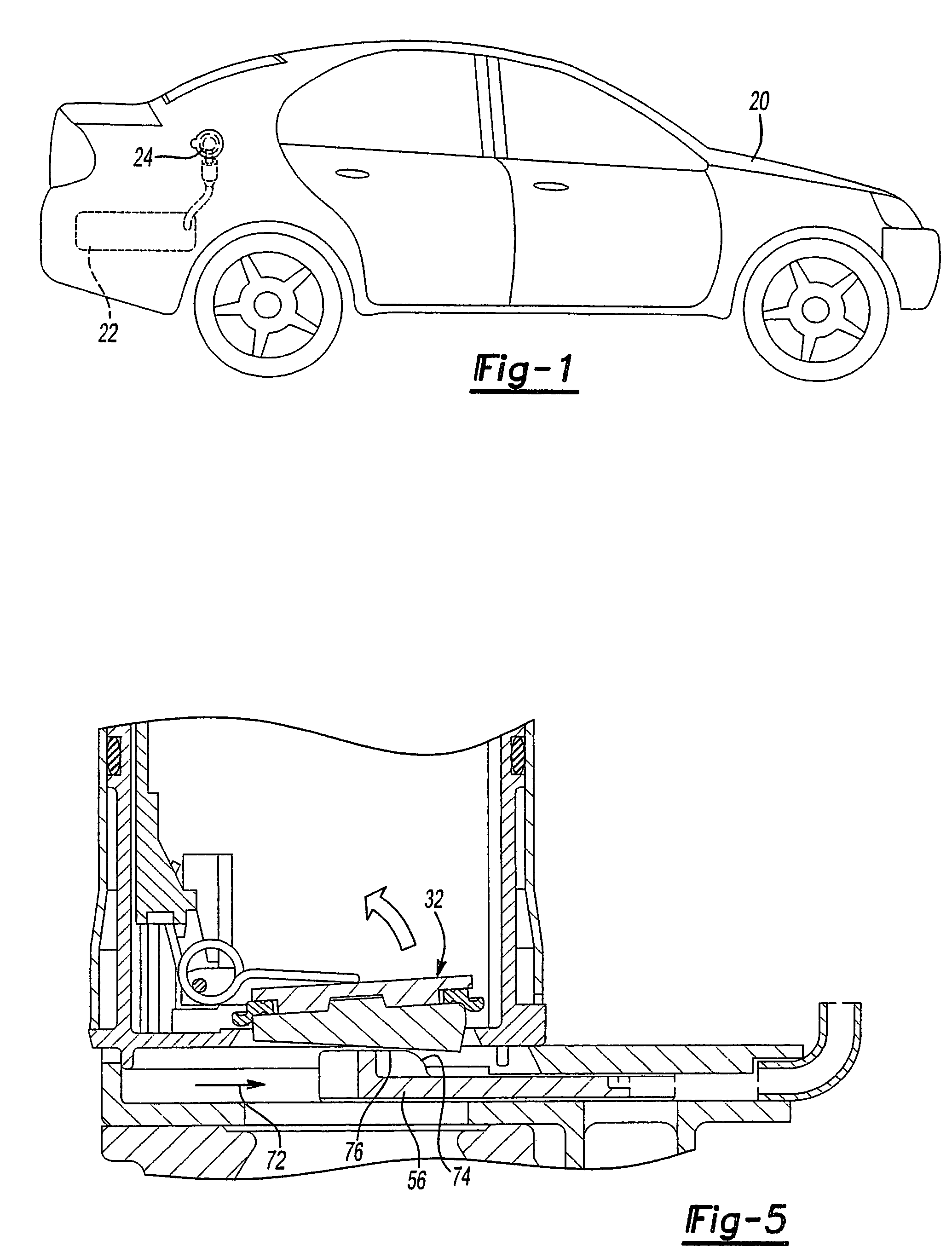
[0039]With reference first to FIG. 1, a conventional automotive vehicle 20 is shown having a fuel tank 22. A capless automotive fuel filling system 24, which will be hereinafter described in greater detail, is associated with the fuel tank 22 to enable the fuel tank 22 to be filled with fuel when desired.

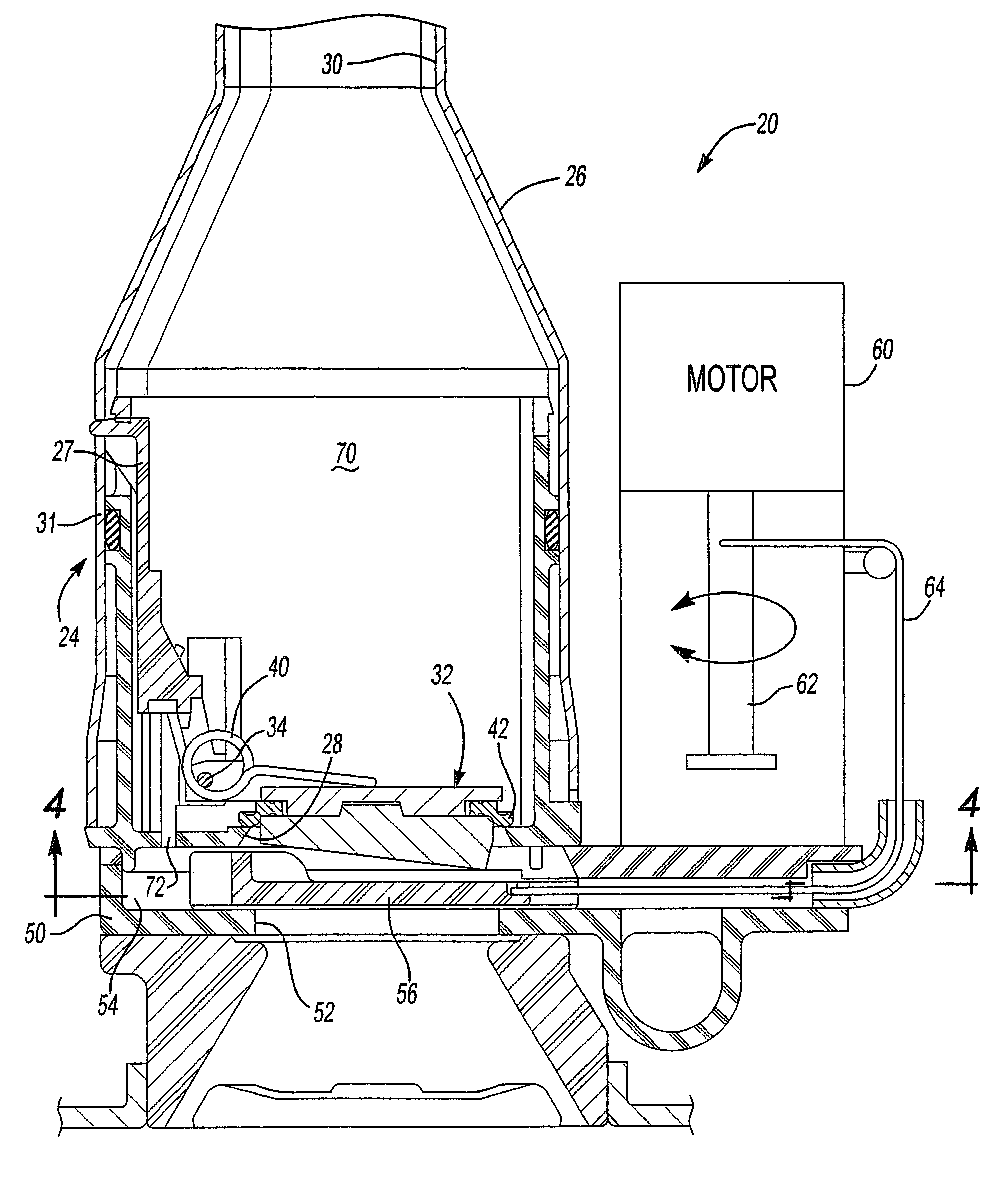
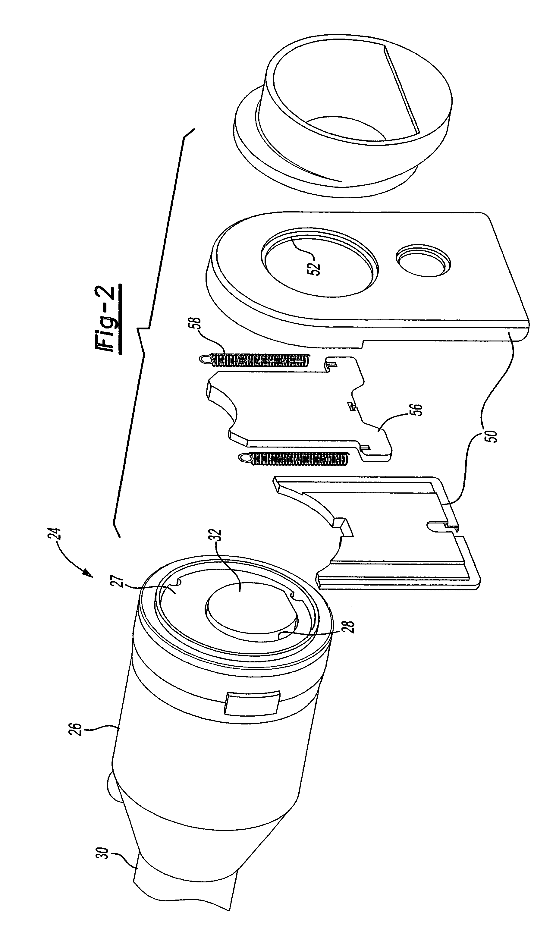
[0040]With reference now to FIGS. 2–4, the fueling system 24 is there shown in greater detail and includes a fuel funnel 26 having a cylindrical funnel insert mounted with its open end and fluidly sealed to the funnel 26 by an annular seal 31. A fluid port 28 is formed in the funnel insert 27 and an inner end 30 of the funnel 26 is fluidly connected to the fuel tank 22.

[0041]As best shown in FIGS. 2 and 3, a fuel valve 32 is mounted to the funnel insert 27 by a pivot pin 34 (FIG. 3) and movable between a closed position, illustrated in FIG. 3, and an open position illustrated in FIG. 8. A spring 40 urges the fuel valve 32 towards its closed position. Furthermore, as best shown in FI...


PUM

PropertyMeasurementUnit
diameteraaaaaaaaaa
torqueaaaaaaaaaa
diametersaaaaaaaaaa

Abstract

A capless automotive fueling system having a funnel with a port open to receive a fuel filling nozzle. A spring loaded valve is movable between an open position in which the port is open and a closed position in which the fuel valve overlies and sealingly covers the port. A shield is movable between a first position in which the shield overlies and covers the valve, and a second position in which the shield is laterally disposed to one side of the valve to permit insertion of the fuel filling nozzle. A motor is drivingly connected to the shield and, on activation, moves the shield from its first and to its second position. Alternatively, two latches engage the valve to retain the valve in a closed position. Upon insertion of a properly sized fuel nozzle, the nozzle engages the latches and pivots them to an open position.

Description

CROSS REFERENCE TO RELATED APPLICATIONS[0001]This application is a divisional of U.S. application Ser. No. 10 / 960,816 filed Oct. 7, 2004.BACKGROUND OF THE INVENTION[0002]I. Field of the Invention[0003]The present invention relates to fueling systems for automotive vehicles and, more particularly, to a capless automotive fueling system.[0004]II. Description of Related Art[0005]All automotive vehicles include fueling systems to allow the fuel tank for the vehicle to be refilled. Typically, the fueling systems include a funnel which is dimensioned to receive a conventional fuel filling nozzle. The funnel in turn is connected to the fuel tank for the vehicle.[0006]Many of these fuel filling systems also include an orifice inserted into or formed in the funnel which is dimensioned to receive the neck of the fuel filling nozzle. A spring loaded flapper valve is oftentimes mounted to the funnel and movable between an open and a closed position. In its closed position, the valve closes the ...

Claims


Application Information

Patent Timeline
Patent Type & Authority Patents(United States)
IPC IPC(8): B65B1/04B60K15/04B60K15/05
CPCB60K15/04B60K15/0409B60K15/05B60K2015/0483B60K2015/0429B60K2015/0445B60K2015/0425
Inventor GABBEY, DAVID JOHNCUNKLE, DANIEL PAUL
Owner MARTINREA IND INC
Why Eureka
Try Eureka