Printing apparatus performing print registration
a printing apparatus and printing register technology, applied in the field of printing apparatus, can solve the problems of unfavorable troublesome operation, long time-consuming and labor-intensive, and large number of patterns to be printed
- Summary
- Abstract
- Description
- Claims
- Application Information
AI Technical Summary
Benefits of technology
Problems solved by technology
Method used
Image
Examples
first embodiment
[First Embodiment]
[0102]In a first embodiment according to the present invention, printing registration between a printing position in the forward scan and a printing position in the reverse scan is performed in a printing system for forming an image by performing complementary printing in the forward scan and the reverse scan by means of one printing head. In this embodiment, one kind of printing medium is used.
(First Construction of Printing Apparatus)
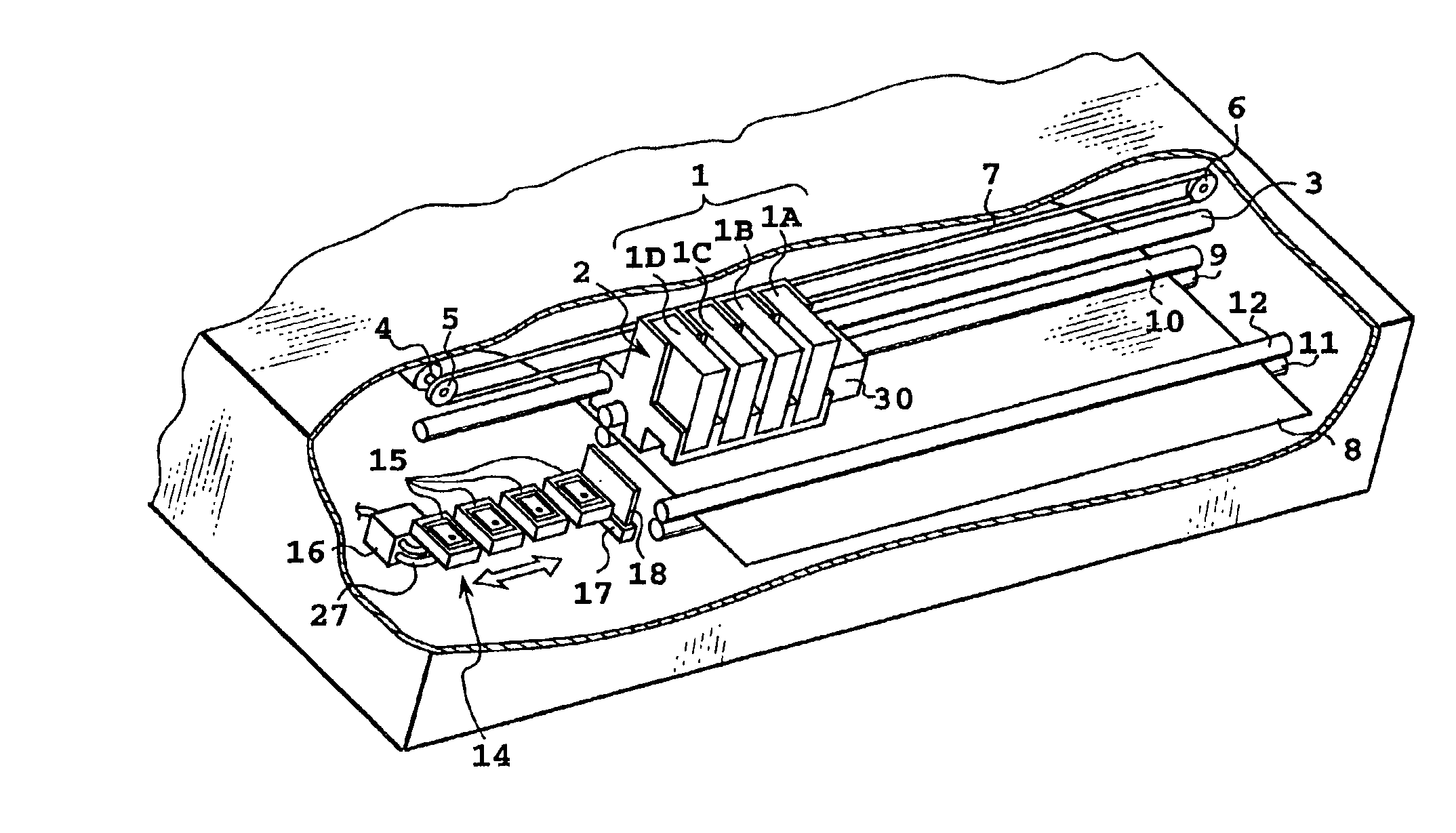
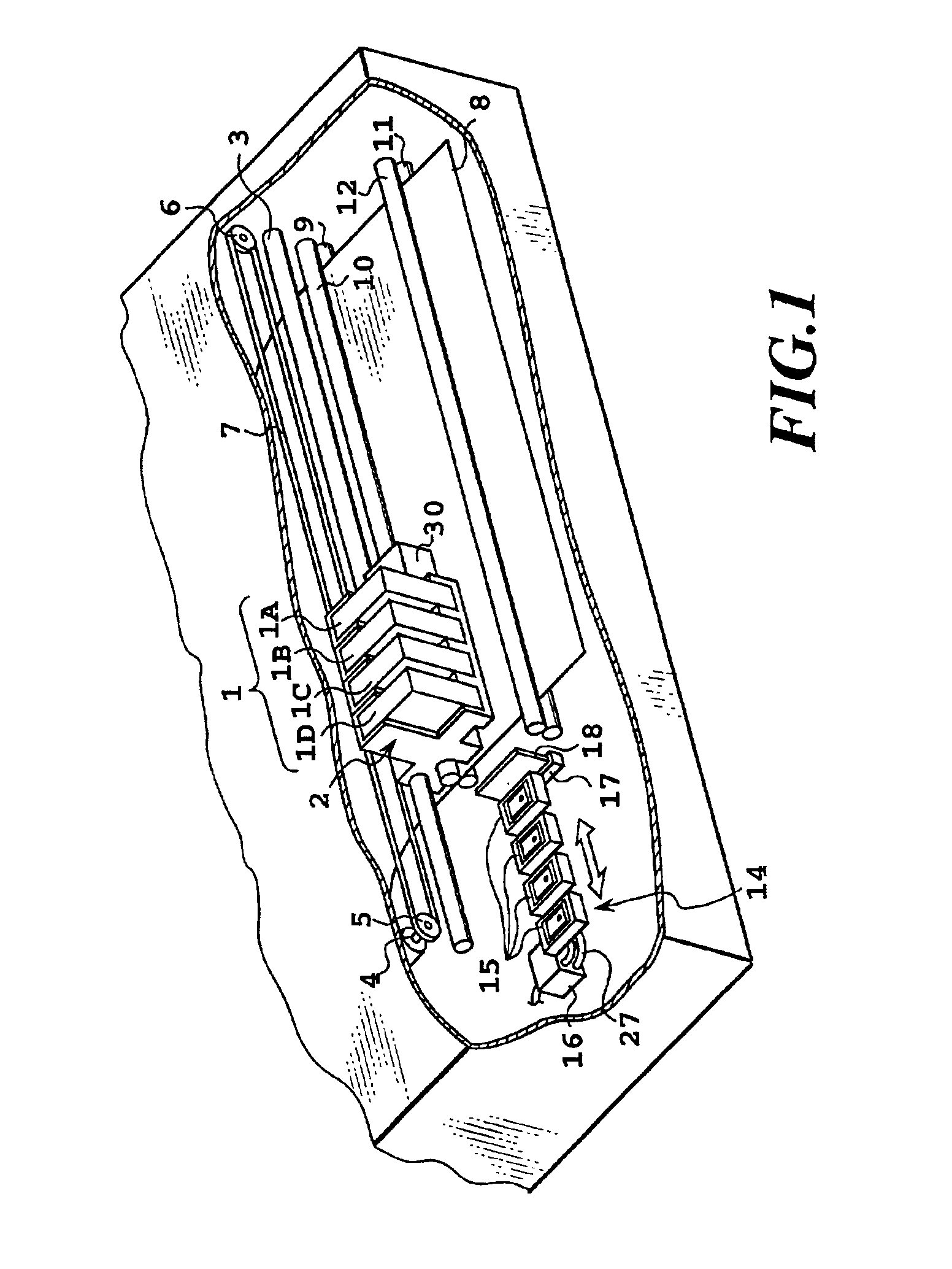
[0103]FIG. 1 is a schematic perspective view showing the construction of main parts of an ink-jet printing apparatus in one preferred embodiment, to which the present invention is applied.
[0104]In FIG. 1, a plurality (four) of head cartridges 1A, 1B, 1C and 1D are mounted on a carriage 2 in a replaceable manner. Each of the head cartridges 1A to 1D has a printing head and an ink tank, and also has a connector for transmitting or receiving a signal for driving the printing head. It should be noted that, in the following explanation, a...
second embodiment
[Second Embodiment]
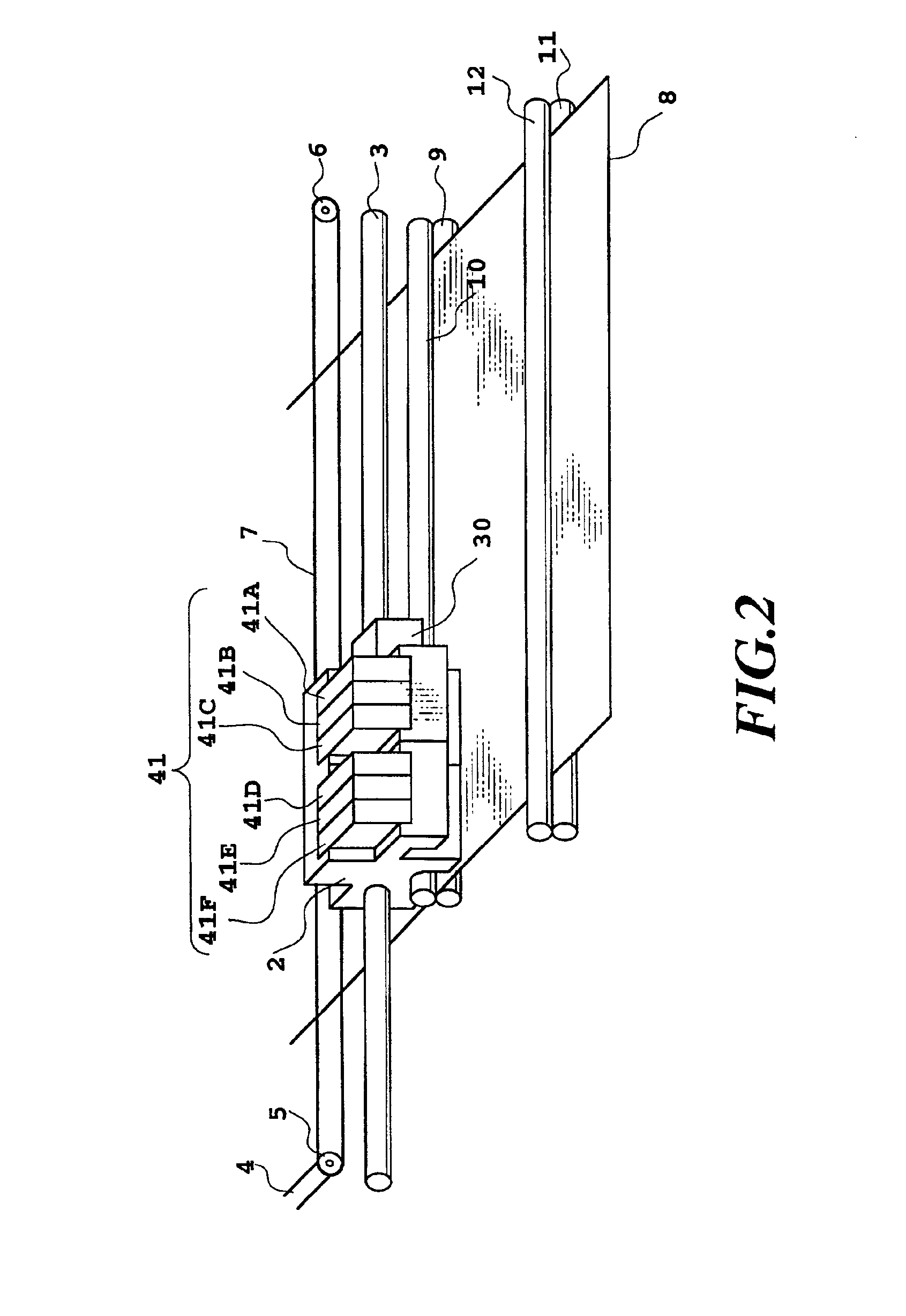
[0165]A second embodiment according to the present invention concerns a printing position in a carriage scanning direction between different heads. Furthermore, it relates to printing registration in the case where a plurality of kinds of printing mediums, inks, printing heads and so on are used. Namely, the size and density of dots to be formed may be varied depending upon the kind of printing medium or the like to be used. Therefore, in advance of judgment of a printing registration condition, judgment is made as to whether a measured reflection optical density is suitable for the judgment of the printing registration condition. As a result, if it is judged that the measured reflection optical density is not suitable for the judgment of the printing registration condition, the level of the reflection optical density is adjusted by thinning the dots in the printing pattern or overprinting the dots, as described above.
[0166]In advance of judgment of the printing r...
third embodiment
[Third Embodiment]
[0184]A third embodiment of the present invention concerns printing registration between a plurality of heads in a direction perpendicular to a carriage scanning direction. It should be noted that explanation will be given of a printing apparatus using only one kind of printing medium, printing head and ink.
(Method for Correcting Printing Position)
[0185]In the printing apparatus in the present embodiment, in order to perform correction of a printing position in the direction perpendicular to the carriage scanning direction (auxiliary scanning direction), ink ejecting openings of the printing head are provided over a range wider than a width (band width) in the auxiliary scanning direction of an image formed by one scan so as to permit correction of the printing position at each interval between the ejection openings by shifting the range of the ejection openings to be used. Namely, as a result of shifted correspondence between the data (image data or the like) to b...
PUM
 Abstract
Description
Claims
Application Information
 - R&D
- Intellectual Property
- Life Sciences
- Materials
- Tech Scout
- Unparalleled Data Quality
- Higher Quality Content
- 60% Fewer Hallucinations
Browse by: Latest US Patents, China's latest patents, Technical Efficacy Thesaurus, Application Domain, Technology Topic, Popular Technical Reports.
© 2025 PatSnap. All rights reserved.Legal|Privacy policy|Modern Slavery Act Transparency Statement|Sitemap|About US| Contact US: help@patsnap.com


