Horizontal bar

a horizontal bar and bar body technology, applied in the field of horizontal bars, can solve the problems of time-consuming and troublesome assembling and disassembling of horizontal bars, and achieve the effect of convenient assembly and disassembly

Inactive Publication Date: 2006-02-07
CHU WALT
View PDF12 Cites 11 Cited by
  • Summary
  • Abstract
  • Description
  • Claims
  • Application Information

AI Technical Summary

Benefits of technology

[0006]A primary object of the present invention is to provide a horizontal bar that includes reduced number of simplified parts and components and can therefore be easily and quickly assembled and disassembled.
[0008]With the above arrangements, the horizontal bar includes simple parts that can be easily assembled and disassembled, and can be connected to other types of sporting goods for more kinds of exercises.

Problems solved by technology

The numerous complicated parts and components disadvantageously result in troublesome and time-consuming assembling and disassembling of the horizontal bar.

Method used


Image

  • Horizontal bar
  • Horizontal bar
  • Horizontal bar

Examples


Embodiment Construction

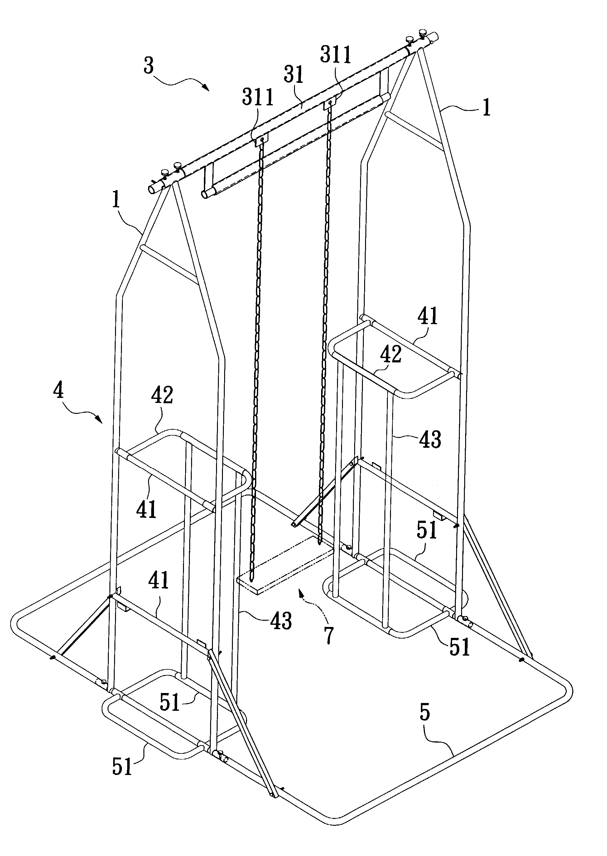
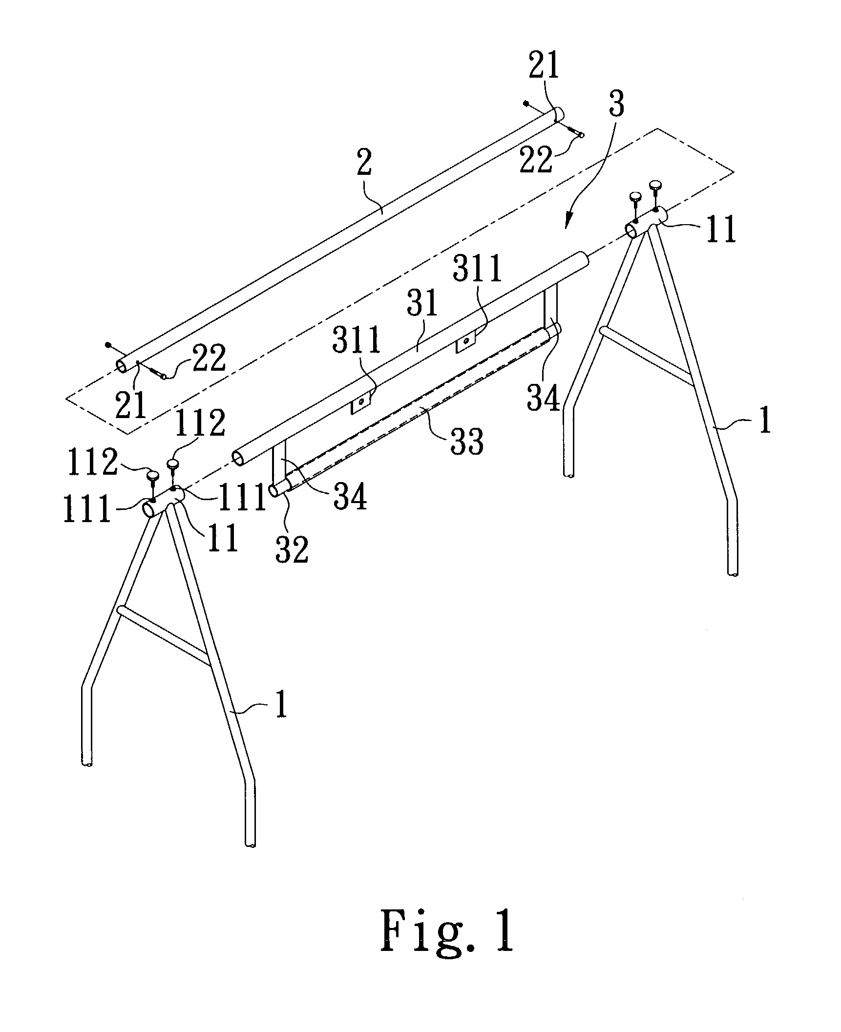
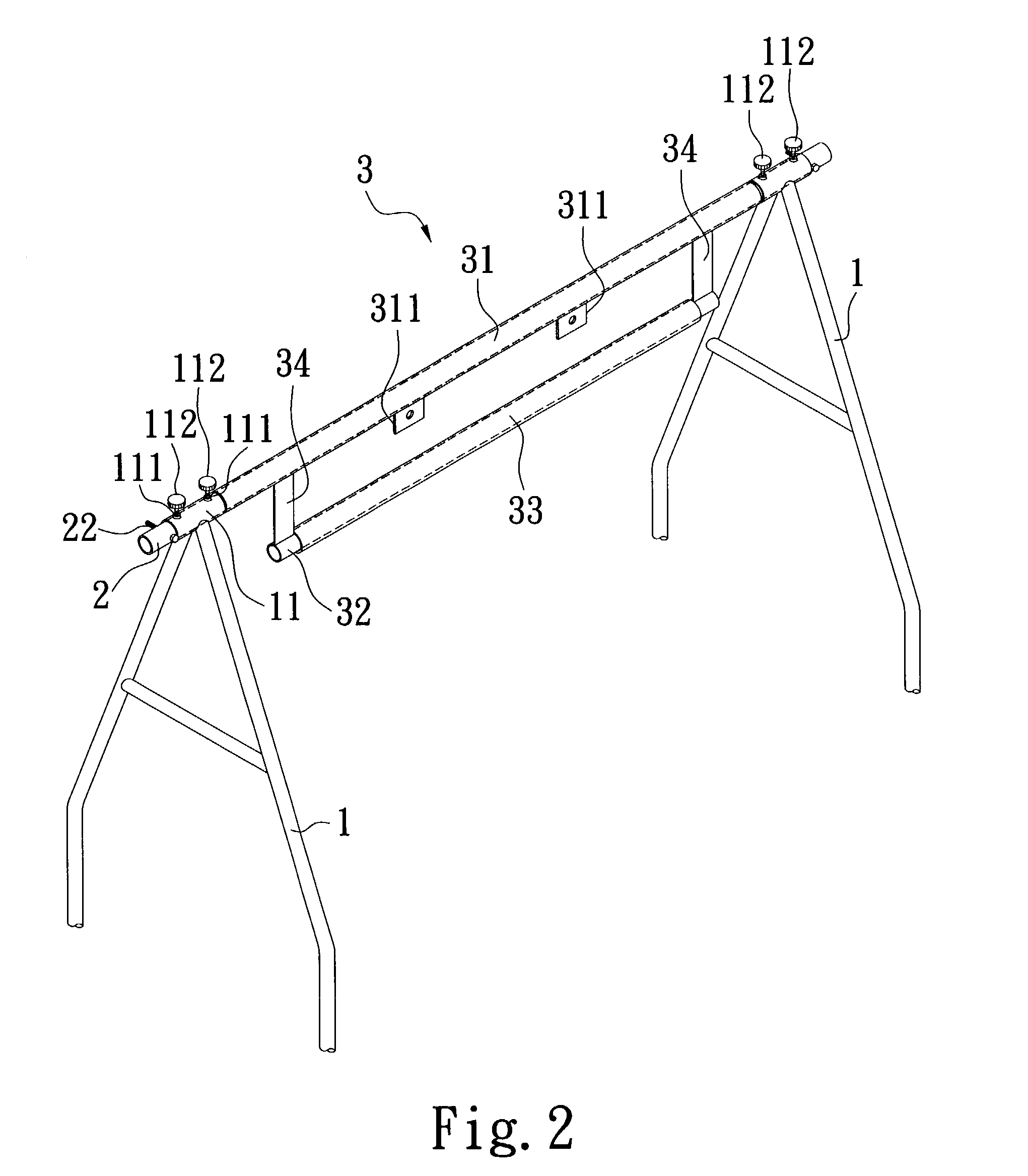
[0014]Please refer to FIGS. 1 and 2 that are exploded and assembled perspective views, respectively, of a horizontal bar according to the present invention. As shown, the horizontal bar of the present invention mainly includes two symmetrical side supports 1, a top bar 2, and a swing member 3.

[0015]Each of the two side supports 1 has a locating hole 11 defined in a locating sleeve connected to a top of the side support 1. Threaded holes 111 are axially spaced on the locating sleeve for screws 112 to extend therethrough.

[0016]The top bar 2 is connected to the top of the two side supports 1 by extending two ends through the locating holes 11 defined in the two locating sleeves, so that the top bar 2 is transversely extended between the tops of the two side supports 1. The top bar 2 is provided near each outer end with two diametrically opposite holes 21.

[0017]The swing member 3 includes two horizontally paralleled and spaced bars, namely, an upper bar 31 and a lower bar 32 connected t...


PUM


Abstract

A horizontal bar includes two side supports, a top bar, and a swing member. The side supports are provided at upper ends with two symmetrical locating holes, through which two outer ends of the top bar are extended to thereby connect the top bar to the side supports. The swing member includes horizontally paralleled upper and lower bars connected to each other via a plurality of connecting plates vertically extended between the upper and lower bars. The upper bar is a hollow tubular member put around the top bar, and the lower bar is covered with a sleeve. The horizontal bar includes simple parts that can be easily assembled and disassembled, and can be connected to other types of sporting goods for more kinds of exercises.

Description

FIELD OF THE INVENTION[0001]The present invention relates to a horizontal bar, and more particularly to a sectional horizontal bar including simple parts that can be easily assembled and disassembled, and being adapted to connect to other types of sporting goods for more kinds of exercises.BACKGROUND OF THE INVENTION[0002]A conventional horizontal bar mainly includes two simple uprights with a top bar transversely extended between upper ends of the two uprights. A user may grip at the top bar to do different motions, such as pulling up, swinging to and fro, etc. To ensure that the horizontal bar has sufficient structural strength and stability for use, the two uprights are normally buried into the ground by a proper depth and the top bar is welded to the uprights. A horizontal bar with the above-described fixed structure is more suitable for erecting and using outdoors and could not be easily moved according to actual need.[0003]U.S. Pat. No. 6,394,932 granted to the same inventor o...

Claims


Application Information

Patent Timeline
Patent Type & Authority Patents(United States)
IPC IPC(8): A63B1/00A63G9/04A63B69/20A63B71/02A63G9/00
CPCA63B1/00A63B71/023A63G9/00A63B69/201A63B69/305
Inventor CHU, WALT
Owner CHU WALT
Why Eureka
Try Eureka