Decoupling element for a fuel injection device

a fuel injection device and decoupling element technology, which is applied in the direction of fuel injection apparatus, machine/engine, charge feed system, etc., can solve the problems of high cost, unfriendly installation, and complex type of noise muffling, and achieve the effect of improving the robustness of the construction

Active Publication Date: 2018-02-06
ROBERT BOSCH GMBH
View PDF9 Cites 0 Cited by
  • Summary
  • Abstract
  • Description
  • Claims
  • Application Information

AI Technical Summary

Benefits of technology

[0009]An example decoupling element according to the present invention for a fuel injection device may have the advantage that an improved noise muffling is achieved in a particularly simple design. According to the present invention, the decoupling element has an approximately bilinear or non-linear, progressive spring characteristic, due to which multiple positive and advantageous aspects result with the installation of the decoupling element in a fuel injection device including injectors for direct fuel injection. The low stiffness of the decoupling element at an idle point enables an effective decoupling of the fuel injector from the cylinder head and thus considerably reduces the noise emitted from the cylinder head during the noise-critical idle operation. The great stiffness at nominal system pressure provides, on the one hand, for an overall low movement of the fuel injector during vehicle operation and thus ensures the durability of the sealing rings, which are used for combustion chamber sealing and as sealing against the fuel rail, and, on the other hand, ensures a stable injection point of the fuel spray in the combustion chamber which is decisive for the stability of some combustion processes.
[0010]The decoupling element is characterized by a very low overall height, whereby it is also usable in small installation spaces similar to a standard disk spring. The decoupling element additionally has a great endurance strength even at high temperatures. The only component required for the decoupling element is a spring washer, which is very simple in terms of manufacturing, inexpensive, and is reliably manufacturable and reproducible in great numbers. The machining of the receiving borehole in the area of the contoured shoulder to be used as the spring seat is likewise possible and comparatively easy with known tools. The complete suspension of the system made up of the fuel injector and the decoupling element may additionally be easily and quickly assembled or disassembled.
[0012]It is particularly advantageous to carry out the contouring of the spring seat to form an air gap between the spring seat and the spring washer. The spring seat may thereby advantageously have an upper shoulder on its end face, or the upper side of the shoulder of the receiving borehole facing the spring washer is designed with a tapered or conical end face or with a pulvinate end face. The design of the decoupling element is carried out in such a way that the height of the air gap may vary slightly without impairing the decoupling effect, or that plastic deformations that are too great occur at the spring washer. This design strategy additionally results in an advantageous way to an improved robustness of the construction with respect to contamination phenomena over the service life.

Problems solved by technology

More complex, and significantly more expensive to manufacture intermediate elements for fuel injection devices are described in German Patent Application Nos.
This type of noise muffling is, however, very complex, installation unfriendly, and expensive.

Method used


Image

  • Decoupling element for a fuel injection device
  • Decoupling element for a fuel injection device
  • Decoupling element for a fuel injection device

Examples


Embodiment Construction

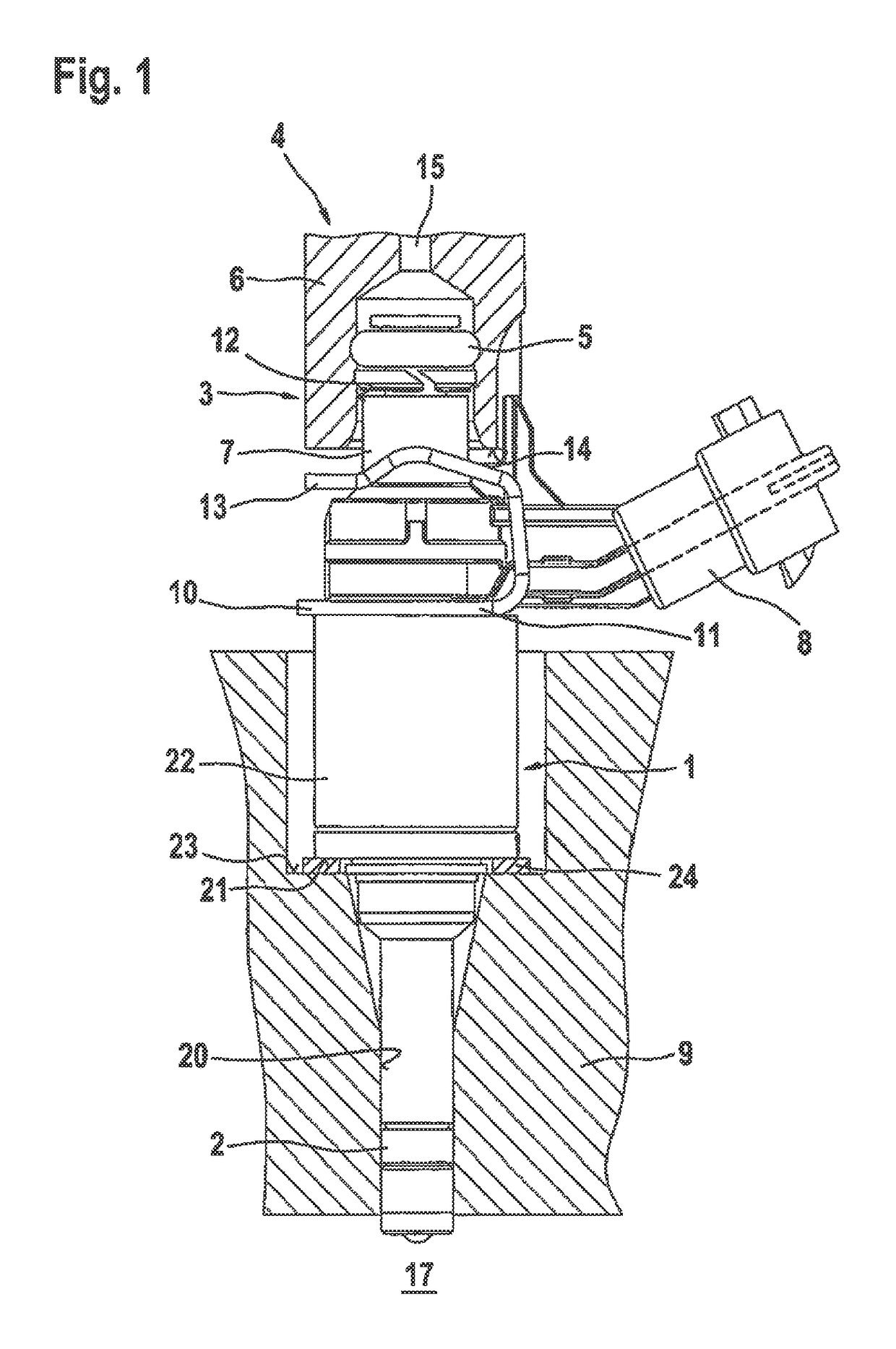
[0019]To assist in understanding the present invention, a conventional specific embodiment of a fuel injection device is subsequently described in greater detail with reference to FIG. 1. In FIG. 1, a valve in the form of an injector 1 for fuel injection systems of mixture-compressing spark-ignition internal combustion engines is depicted in a side view as an exemplary embodiment. Fuel injector 1 is part of the fuel injection device. Fuel injector 1, which is designed in the form of a direct injecting injector for direct injection of fuel into a combustion chamber 17 of the internal combustion engine, is installed with a downstream end in a receiving borehole 20 of a cylinder head 9. A sealing ring 2, in particular made of Teflon™, provides an optimal sealing of fuel injector 1 against the wall of receiving borehole 20 of cylinder head 9.

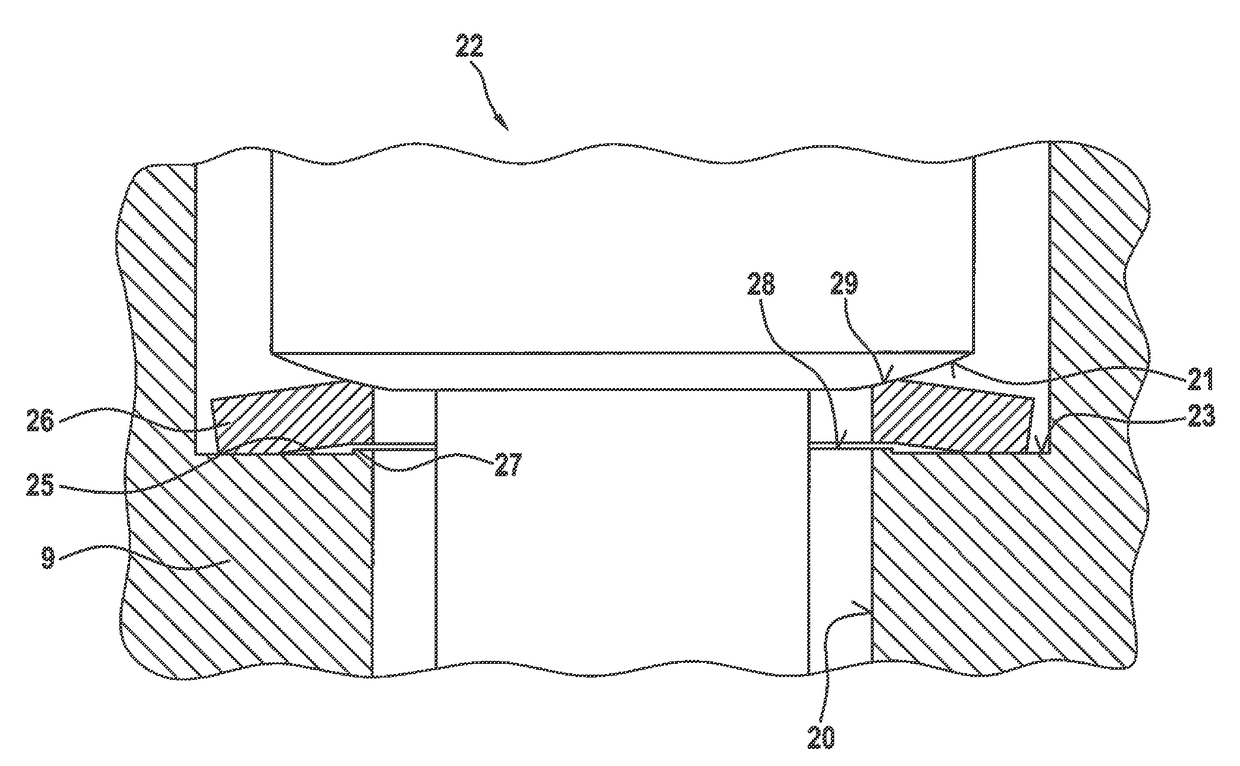
[0020]A flat intermediate element 24, which is designed as a support element in the form of a washer, is inserted between a shoulder 21 of a valve ...


PUM


Abstract

The decoupling element for a fuel injection device according to the invention is characterized in particular in that a low noise design is implemented. The fuel injection device includes at least one fuel injector and a receiving borehole in a cylinder head for the fuel injector, and the decoupling element between a valve housing of the fuel injector and a wall of the receiving borehole. The decoupling element is a decoupling system made up of a contoured spring seat on a shoulder of the receiving borehole and a spring washer resting on the shoulder. The fuel injection device is suited in particular for direct injection of fuel into a combustion chamber of a mixture-compressing spark-ignition internal combustion engines.

Description

CROSS REFERENCE[0001]The present application claims the benefit under 35 U.S.C. §119 of German Patent Application No. DE 102015217500.6 filed on Sep. 14, 2015, which is expressly incorporated herein by reference in its entirety.FIELD[0002]The present invention is directed to a decoupling element for a fuel injection device.BACKGROUND INFORMATION[0003]In FIG. 1, a conventional fuel injection device from the related art is shown as an example, in which a flat intermediate element is provided on a fuel injector installed in a receiving borehole of a cylinder head of an internal combustion engine. Such intermediate elements are placed in a conventional way as support elements in the form of a washer on a shoulder of the receiving borehole of the cylinder head. With the aid of such intermediate elements, manufacturing and assembly tolerances are compensated and a mounting free of lateral forces is ensured even at a slight inclination of the fuel injector. The fuel injection device is sui...

Claims


Application Information

Patent Timeline
Patent Type & Authority Patents(United States)
IPC IPC(8): F02M61/14
CPCF02M61/14F02M2200/858F02M2200/857F02M2200/50
Inventor HORST, HANS-GEORGFISCHER, MICHAEL
Owner ROBERT BOSCH GMBH
Why Eureka
Try Eureka