Antenna element

a technology of antenna elements and elements, applied in the structure of antennas, radiating elements, electrical devices, etc., can solve the problems of reducing the bandwidth of the antenna, deteriorating the polarization properties of the antenna element, and different impedance behavior of the antenna port, so as to achieve a wide frequency band bandwidth, reduce the cost, and improve the polarization properties

Inactive Publication Date: 2006-02-07
GILAT SATELLITE NETWORKS
View PDF7 Cites 87 Cited by
  • Summary
  • Abstract
  • Description
  • Claims
  • Application Information

AI Technical Summary

Benefits of technology

[0006]The object of the present invention is to provide a simpler and less expensive dual polarized antenna element with good polarization properties in wider frequency band bandwidth.
[0020]Advantages of the antenna element according to the invention are the simpler from technological point of view structure, simpler and less expensive construction. The antenna element has reduced inductive mutual coupling between the two symmetrical parts of the structure hence two main properties of the element are improved:
[0022]Better impedance matching due to compensated reactive part of the impedance of the input ports is achieved that betters the bandwidth in respect to VSWR.
[0023]Another advantage is the opportunity to compensate the increased inductive mutual influence caused from moving the crossing point of the slots and feed tracks closer to the slots center whereby the amplitude distribution of the field along the slot is improved. As result more symmetrical radiation pattern could be formed.

Problems solved by technology

Slot fed antenna elements have the drawback of non-optimal feeding the slot aside it center, having the field along the slot deformed and decreased impedance toward the slot ends narrowing the bandwidth.
Another drawback caused from slots crossing is the mutual influence between said slots and respective ports, what directly deteriorate the polarization properties of the antenna element.
Drawback of this antenna element is the different way of the slots excitation, which leads to different impedance behavior of the antenna ports.

Method used


Image

  • Antenna element
  • Antenna element
  • Antenna element

Examples


Embodiment Construction

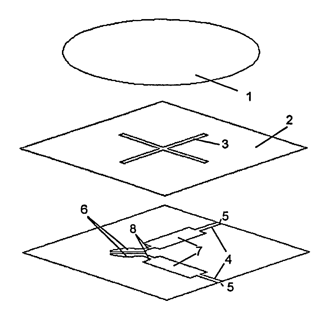
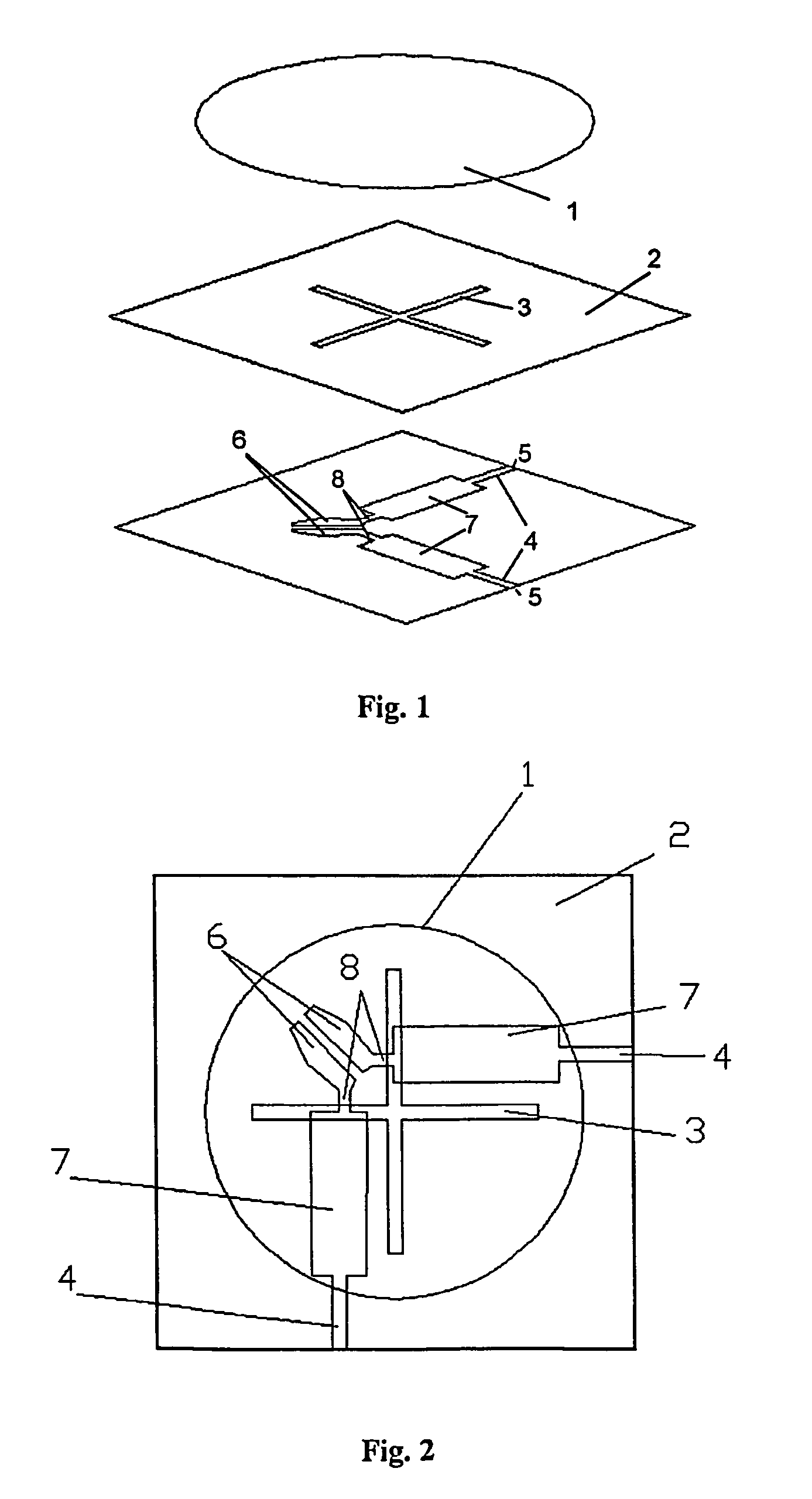
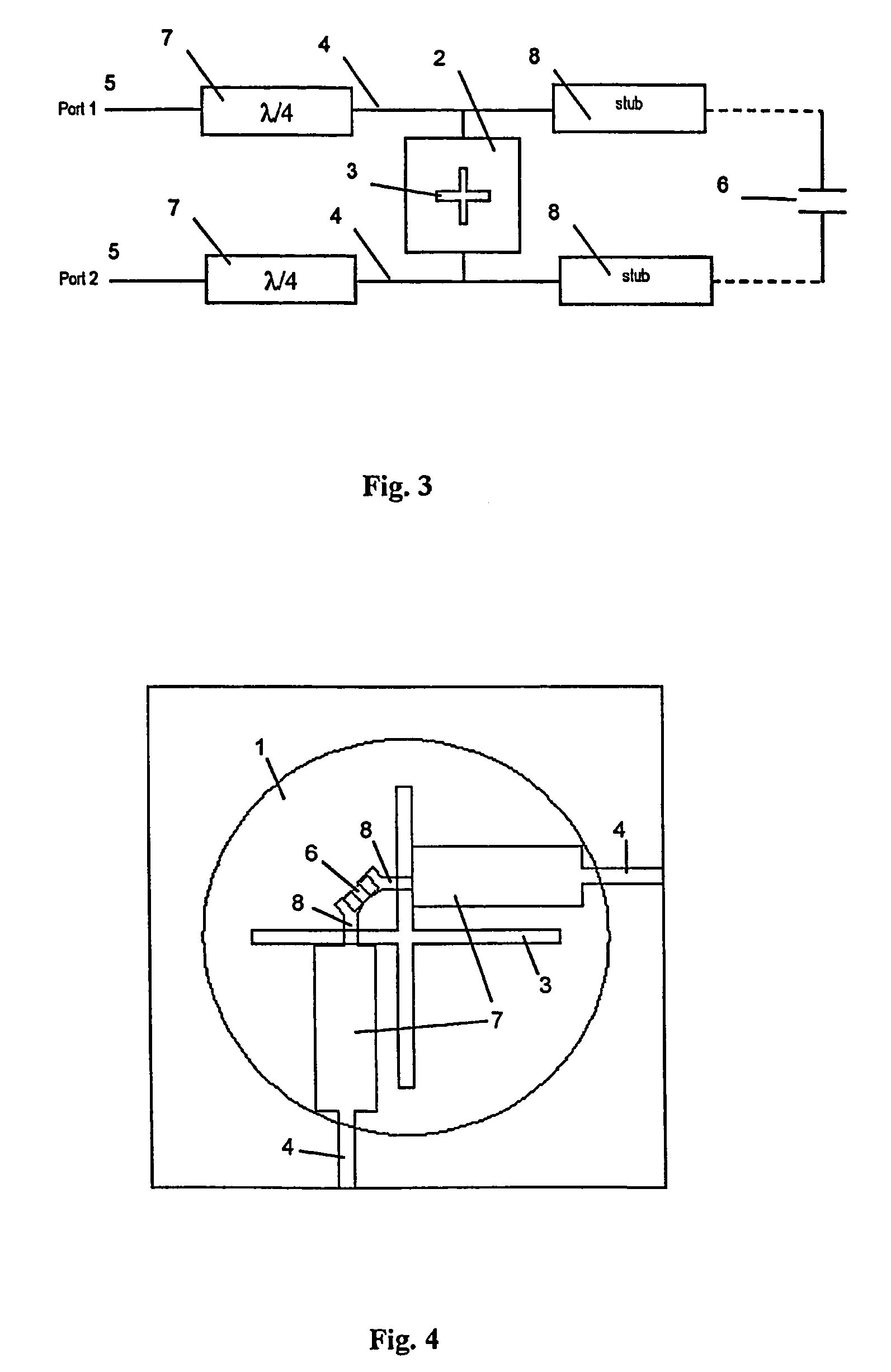
[0033]Referring to FIG. 1–2, the antenna element comprises radiating patch 1 with providing the expected electrical performance arbitrary shape, but preferably circular from antenna array populating point of view, a ground plane 2 disposed under the radiating patch and comprising two slot apertures arrangements 3 crossing each to other orthogonally in their centers, feed tracks 4 disposed under the ground plane 2 so to cross one of the arms of the corresponding slot 3 laying above. The feed tracks could be symmetrical or asymmetrical strip lines. The preferred slot length is less a half effective wavelength (of the electromagnetic field). Each feed track 4 is disposed in certain way corresponding to the slot influence over the transmition line parameters. The first end of the feed tracks 4 is connected to a input / output port 5 of the antenna element, whereas the second end, placed after the crossing point of the track 4 with the slot 3, is connected to the corresponding end of the o...


PUM


Abstract

The antenna element comprises: an electrically conductive ground plane (2) on which two orthogonal symmetrically crossing slots (3) are formed; a radiating patch (1) supported in a spaced relationship on the one side of the said ground plane; conductive feeding tracks (4) supported on the other side of the said ground plane and electromagnetically coupled with the slots (3). One of the ends of each feeding track (4) is input / output port (5) of the antenna element and the other end is disposed after the slot (3), so as the feeding tracks (4) to cross the slots (3). A compensating capacitive element (6) couples the ends of the feeding tracks (4) laid after the slots (3).

Description

[0001]This application is the national phase under 35 U.S.C.§371 of PCT International Application No. PCT / BG02 / 00031 which has an International filing date of Dec. 17, 2002 which designated United States of America.TECHNICAL FIELD[0002]The present invention relates to an antenna element for use in electromagnetic radiation antenna structures capable for receiving and transmitting radio signals that may include dual orthogonal polarized components, especially for use in antenna arrays.PRIOR ART[0003]The identified patch antenna elements comprise radiating patch having the appropriate shape and size and placed above a ground plane or dielectric substrate or spacing element. The patch provides the essential electrical and radiating properties. In this case the exciting signals pass trough slots arranged to cross each other orthogonally in their centers. Each slot excites corresponding mode within the antenna element. The slots are fed through feed tracks that may generally form any typ...

Claims


Application Information

Patent Timeline
Patent Type & Authority Patents(United States)
IPC IPC(8): H01Q1/38H01Q9/04
CPCH01Q9/0435H01Q9/0407
Inventor BOYANOV, VICTOR
Owner GILAT SATELLITE NETWORKS
Why Eureka
Try Eureka