Protective head covering having impact absorbing crumple zone

a protection head and crumple technology, applied in the field of protective head coverings with impact absorption crumple zones, can solve the problems of often worsening the impact of the results

Inactive Publication Date: 2006-02-14
PUCHALSKI TECHN
View PDF21 Cites 73 Cited by
  • Summary
  • Abstract
  • Description
  • Claims
  • Application Information

AI Technical Summary

Benefits of technology

[0008]Accordingly, the present invention strives to overcome some of the disadvantages of prior art helmets by a) providing a protective head covering or helmet that is closer in weight and size to the user's anatomical head, thereby minimizing resultant disproportion between the head with helmet and the neck / torso and by b) redirecting or dissipating injurious forces away from the head and brain, by using multiple connected or interlocking component panels that will move relative to each other in predetermined directions and increments, effectively producing a ‘crumple’, ‘slide’ or ‘shear’, hereinafter are generally referred to as a “crumple zone”.
[0009]A practical advantage with the present invention that also improves safety, is that the multiple portions or panels, enable better customizing to fit different head shapes such as oval, oblong and round, not just adapt to sizes. Parents will be able to customize the helmets as their children grow, thus avoiding the dangerous habit of buying oversized helmets so that the child will ‘grow into it’. A frontal fall in a helmet that is too large, forces the helmet backwards and can force the back of the helmet into the neck at the base of the skull, at the anatomical area of the brain stem, with tragic results often worse than if a helmet had not been worn at all.
[0010]A further safety feature of the present invention exists in that because of the interconnected or interlocking panels, absorbing or re-directing force vectors along predetermined, incremental stages, any rotational vectors at the time of impact will be decreased or changed to linear vectors, thereby reducing the risk of the very damaging rotational injuries to the nerve roots and / or brain stem. The present helmet most preferably is designed to absorb kinetic and / or potential energy at the time of the fall / impact, and transfer it along more controlled, less damaging vectors away from the head and brain.

Problems solved by technology

A frontal fall in a helmet that is too large, forces the helmet backwards and can force the back of the helmet into the neck at the base of the skull, at the anatomical area of the brain stem, with tragic results often worse than if a helmet had not been worn at all.

Method used


Image

  • Protective head covering having impact absorbing crumple zone
  • Protective head covering having impact absorbing crumple zone
  • Protective head covering having impact absorbing crumple zone

Examples


Embodiment Construction

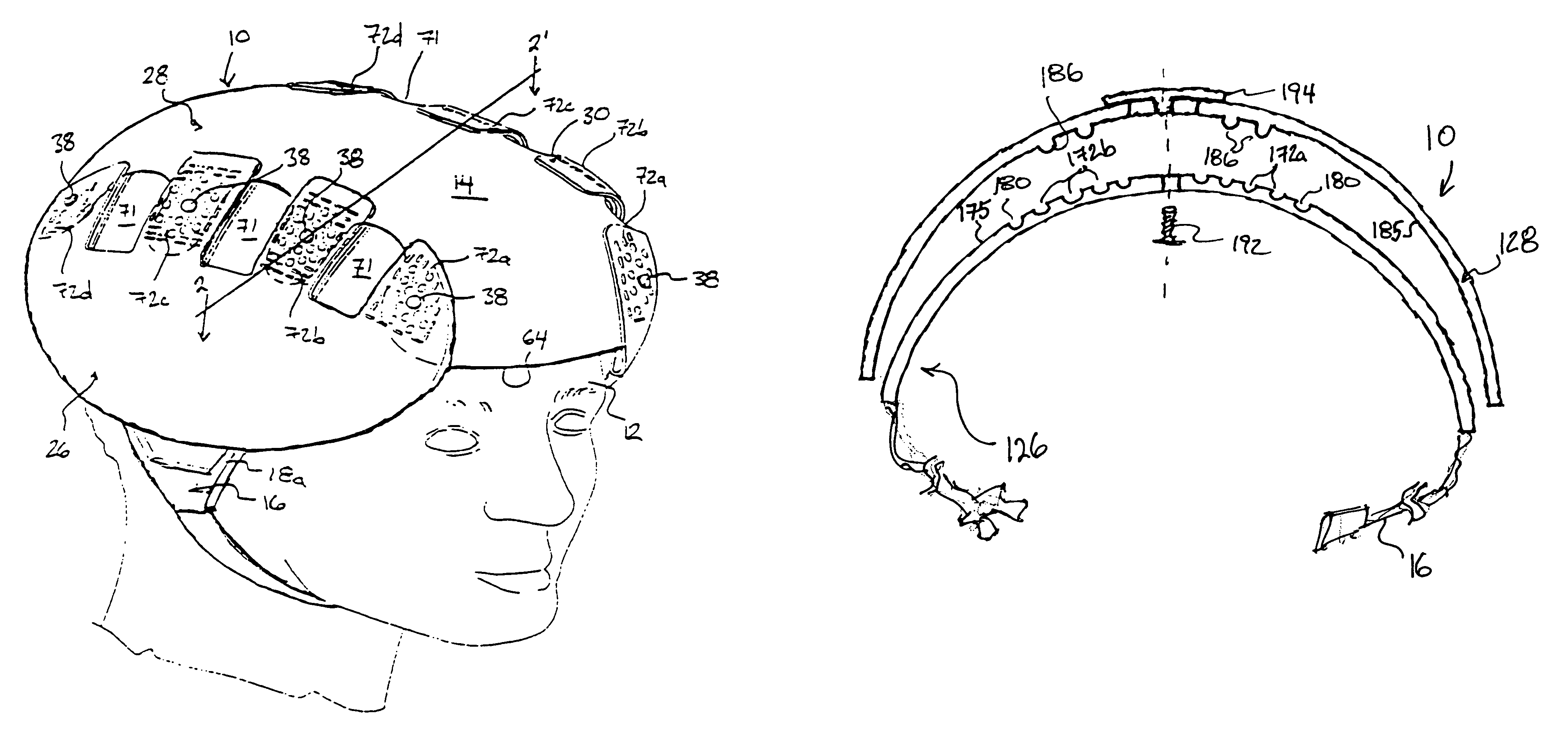
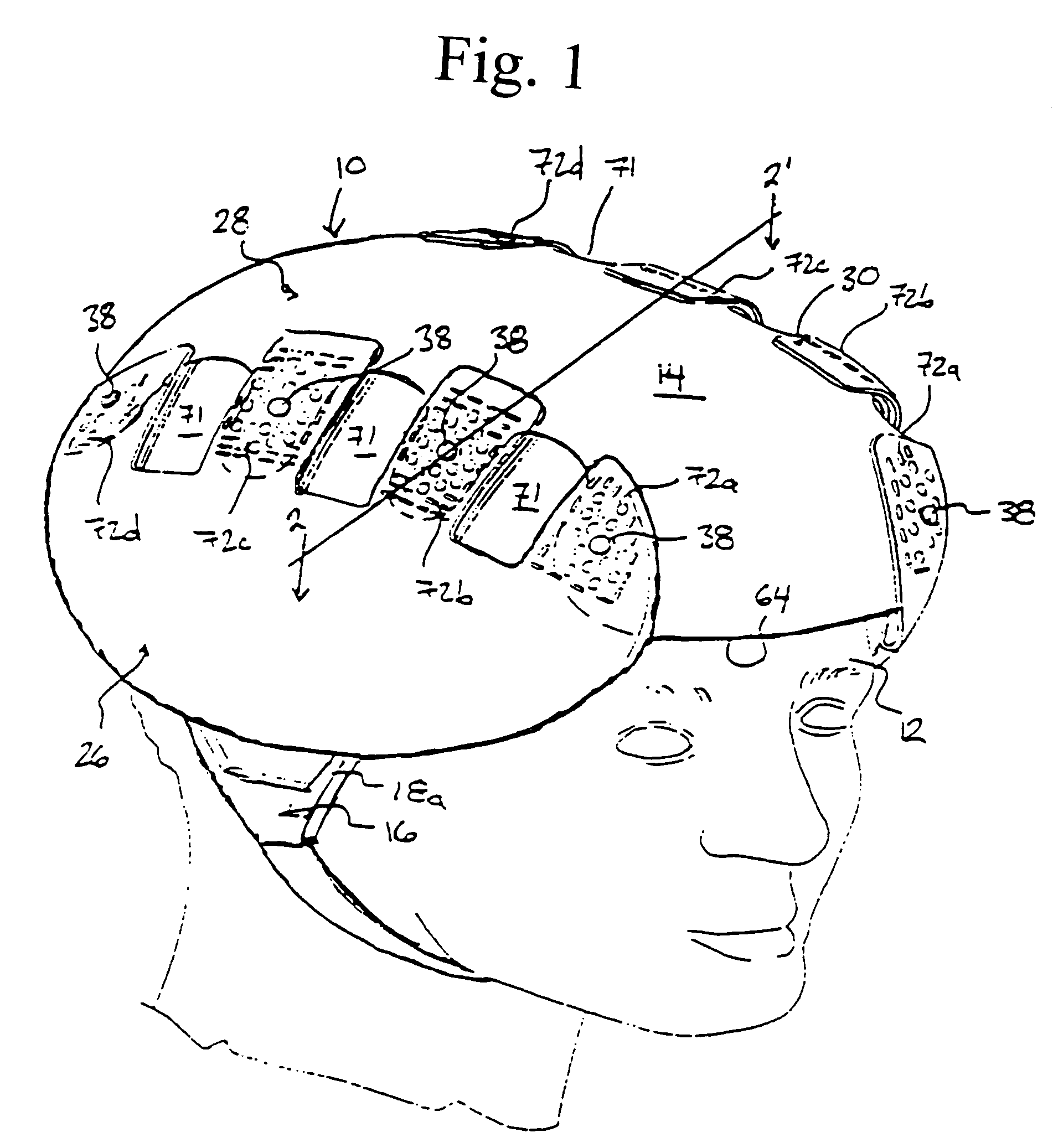
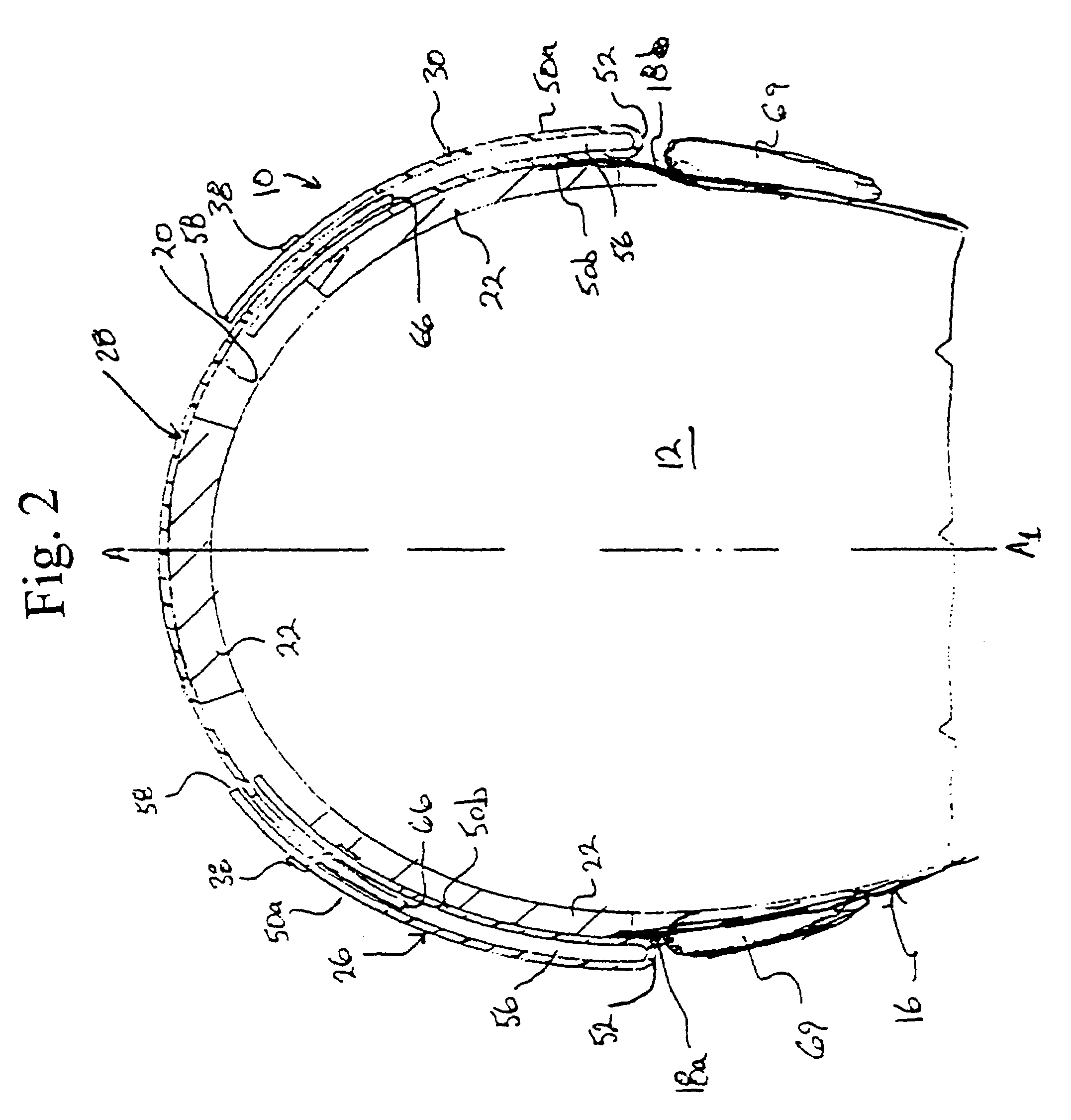
[0044]Reference may first be had to FIG. 1 which illustrates a bicycle helmet construction 10 for use in protecting a user's head 12 from impact forces, which for example would occur if the wearer was struck by a car or otherwise was thrown from a bicycle (not shown). The helmet construction 10 includes a generally domed shaped shell 14 which is secured in place on top of the user's head 12 by a releasable chin strap 16. The chin strap 16 is of a conventional two-piece design and is secured at each of its ends 18a,18b (FIG. 2) to a respective longitudinal side portion of the shell 14. As shown best in FIG. 2, the shell 14 has a size and contour selected so as to substantially cover the top of the user's head 12 and extends symmetrically in the front-to-back direction about a vertical central axis A–A1 (FIG. 2). The inner surface 20 of the shell 14 which is immediately adjacent to the user's head 12 is lined with strips of resiliently compressible foam cushioning 22. The cushioning 2...


PUM


Abstract

A helmet construction for protecting a user's head, and the brain within the cranium from impact forces, includes a shell contoured to the shape of the user's head, with cushioning along at least part of the shell interior and a chinstrap. The shell consists of three (or more) discrete panels that are physically and firmly coupled together providing rigid protection under most circumstances, but upon impact the panels move relative to one another, but not relative to the user's head, thereby permitting impact forces to be dissipated and / or redirected away from the cranium and brain within. Upon impact to the helmet, there are sequential stages of movement of the panels relative to each other, these movements initially being recoverable, but with sufficient vector forces the helmet undergoes structural changes in a pre-determined fashion, so that the recoverable and permanent movements cumulatively provide a protective ‘crumple zone’ or ‘shear zone’. The first two stages of protection arise from the design of the fasteners that have the ability to invaginate and collapse within themselves, and their design having a 45 degree angle, which will allow movement of a region of connected panels to translate along the fastener shaft. Both of these movements will be recoverable and provide a ‘functional crumple zone’. The final stage of protection arises from the braking function of the pins, as they are forced from one aperture through to the next, the direction and extent of which is determined by the impact force and direction. This final level of panel movement and protection is not recoverable and thus provides a ‘structural crumple zone’. Finally the fastener size and thickness, together with the thickness of webbing and distance between apertures, functions to provide varying degrees of resistance to impact forces, thus making the helmet design suitable for activities with different levels of impact speed and risk potential.

Description

RELATED APPLICATIONS[0001]This application is a continuation-in-part of U.S. patent application Ser. No. 10 / 867,667, filed 16 Jun. 2004 and entitled “Protective Head Covering Having Impact Absorbing Crumple or Shear Zone”, and which is filed as a continuation-in-part of U.S. patent application Ser. No. 10 / 372,938, filed 26 Feb. 2003, entitled “Sports Helmet Having Impact Absorbing Crumple or Shear Zone”, and which issued to U.S. Pat. No. 6,751,808 on 22 Jun. 2004.SCOPE OF THE INVENTION[0002]The present invention relates to a protective head covering which, for example, may be used as a hard hat or sports helmet, and which is characterized by two or more parts or panel sections which are joined so that upon the application of a minimum impact force, the parts permit predetermined and controlled movement relative to each other in increments, via a series of mechanisms, to function overall as an impact absorbing ‘crumple’ or ‘shear zone’.[0003]Thus while providing the usual protection ...

Claims


Application Information

Patent Timeline
Patent Type & Authority Patents(United States)
IPC IPC(8): A42B3/00A42B3/06A42B3/32
CPCA42B3/324A42B3/064
Inventor PUCHALSKI, IONE G.
Owner PUCHALSKI TECHN
Why Eureka
Try Eureka