Microscope stand having balancing device

a technology of balancing device and microscope stand, which is applied in the field of microscope stand, can solve the problems of poor application of surgical microscopes, design that offers no simple adjustment for changing loads, etc., and achieves the effects of high loading, improved tilt safety, and exceptional balancing

Inactive Publication Date: 2006-02-21
LEICA INSTR SINGAPORE PTE
View PDF22 Cites 7 Cited by
  • Summary
  • Abstract
  • Description
  • Claims
  • Application Information

AI Technical Summary

Benefits of technology

[0032]A preferred and simple construction provides for a roller which is displaceably mounted on a balance arm and acts on a bracket which cannot be displaced, on which the cable pull acts. By means of this construction, when the support arm is pivoted, the proportional change at the action point of the roller on the bracket is automatically adapted, so that the opposing moments have the same proportion to eac

Problems solved by technology

However, this concerns the provision of force support for an adjusting movement which is exerted by an operator on a handle.
It could therefore be applied only poorly for use on a surgical microscope.
This design offers no simple adjustability f

Method used


Image

  • Microscope stand having balancing device
  • Microscope stand having balancing device
  • Microscope stand having balancing device

Examples


Embodiment Construction

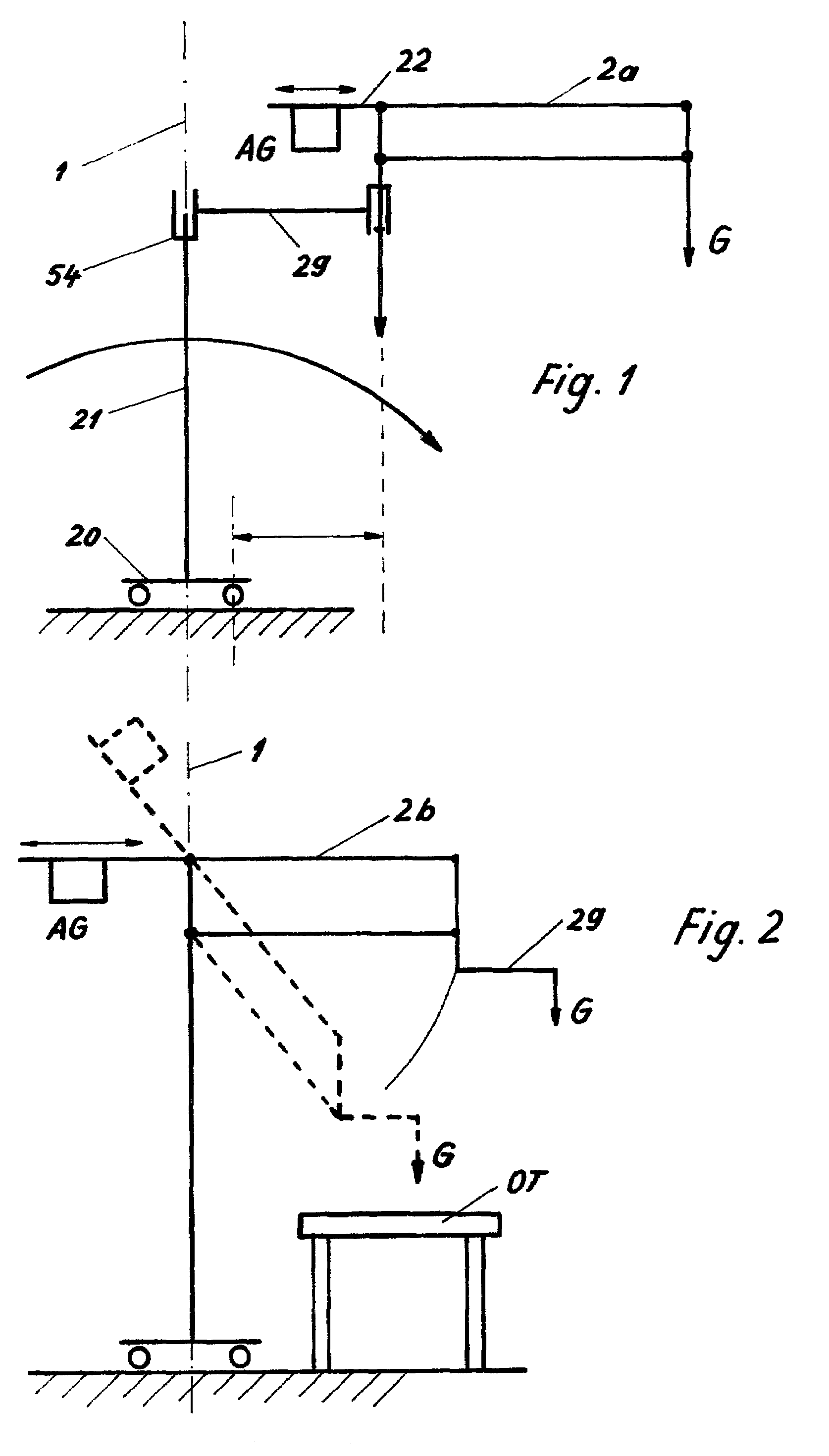
[0047]FIG. 1 shows an example of a conceivable balancing measure on the balance principle, which would be carried out about the vertical axis 1 of the point of attachment of the support arm 2a. Such a measure could initially not improve the tilt safety of the stand, however, since, because of the horizontal support arm 29, the additional weights AG which might be fitted are initially still on the same side of the vertical upright column 21, on which the load G also acts. (Tilting moment according to the arrow over the effective distance k). Only if the balance arm 22 were to be made appropriately long and braked at the pivoting point, in which case it would also project beyond the axis of the upright column 21, could the tilt safety also be improved at the same time with such a balancing system. Here, however, the volume of the overall design would disadvantageously be increased considerably. When the brake were released, tilting might occur. Apart from this, in the case of the conv...


PUM


Abstract

The invention relates to a stand having a pivotable support arm (2) and a balance weight (AG), in which the balance weight (AG) acts via a cable pull (24) for the weight compensation of the load (G), the balance weight (AG) being arranged in the area of the vertical upright column (21) of the stand.

Description

CROSS REFERENCE TO RELATED APPLICATIONS[0001]This invention claims priority of the German application 200 19 105.5 filed Nov. 12, 2000 which is incorporated by reference herein.[0002]The complete disclosures of the following three copending, commonly-owned U.S. patent applications filed concurrently with the present application are hereby incorporated by reference into the present specification: U.S. patent application Ser. No. 10 / 010,103 filed Nov. 8, 2001, now U.S. Pat. No. 6,708,936; U.S. patent application Ser. No. 10 / 008,285 filed Nov. 8, 2001, now U.S. Pat. No. 6,637,274; and U.S. patent application Ser. No. 10 / 007,168 filed Nov. 8. 2001, now U.S. Pat. No. 6,691,960.FIELD OF THE INVENTION[0003]The invention relates to a stand, in particular for surgical microscopes. Surgical microscopes must be capable of pivoting easily over a predefined range and they should maintain the position then set. For this reason, in a group of known stands, balance weights are provided which compen...

Claims


Application Information

Patent Timeline
IPC IPC(8): A47F5/00A61B19/00F16M11/04G02B21/24G02B7/00
CPCF16M11/04F16M11/08F16M11/2064G02B7/001F16M11/42F16M11/28A61B19/5223F16M2200/044F16M2200/068A61B90/20A61B90/25
Inventor METELSKI, ANDRZEJ
Owner LEICA INSTR SINGAPORE PTE
Why Eureka
Try Eureka