Power device for vehicle sliding door

a technology for sliding doors and power devices, which is applied in the direction of doors, wing accessories, lock applications, etc., can solve the problem of heavy load placed on batteries

Inactive Publication Date: 2006-02-28
MITSUI KINZOKU ACT
View PDF4 Cites 46 Cited by
  • Summary
  • Abstract
  • Description
  • Claims
  • Application Information

AI Technical Summary

Benefits of technology

[0007]Accordingly, an object of the present invention is to provide a power device that can sequentially actuate a plurality of power devices by continuously rotating a single motor.

Problems solved by technology

However, when the power close device and the power release device are composed of the single motor, a problem arises in that a heavy load is placed on a battery.

Method used


Image

  • Power device for vehicle sliding door
  • Power device for vehicle sliding door
  • Power device for vehicle sliding door

Examples


Embodiment Construction

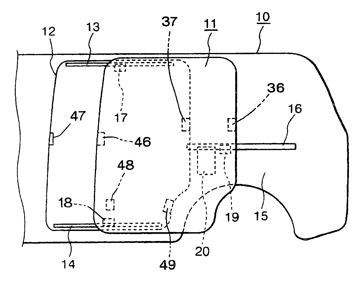
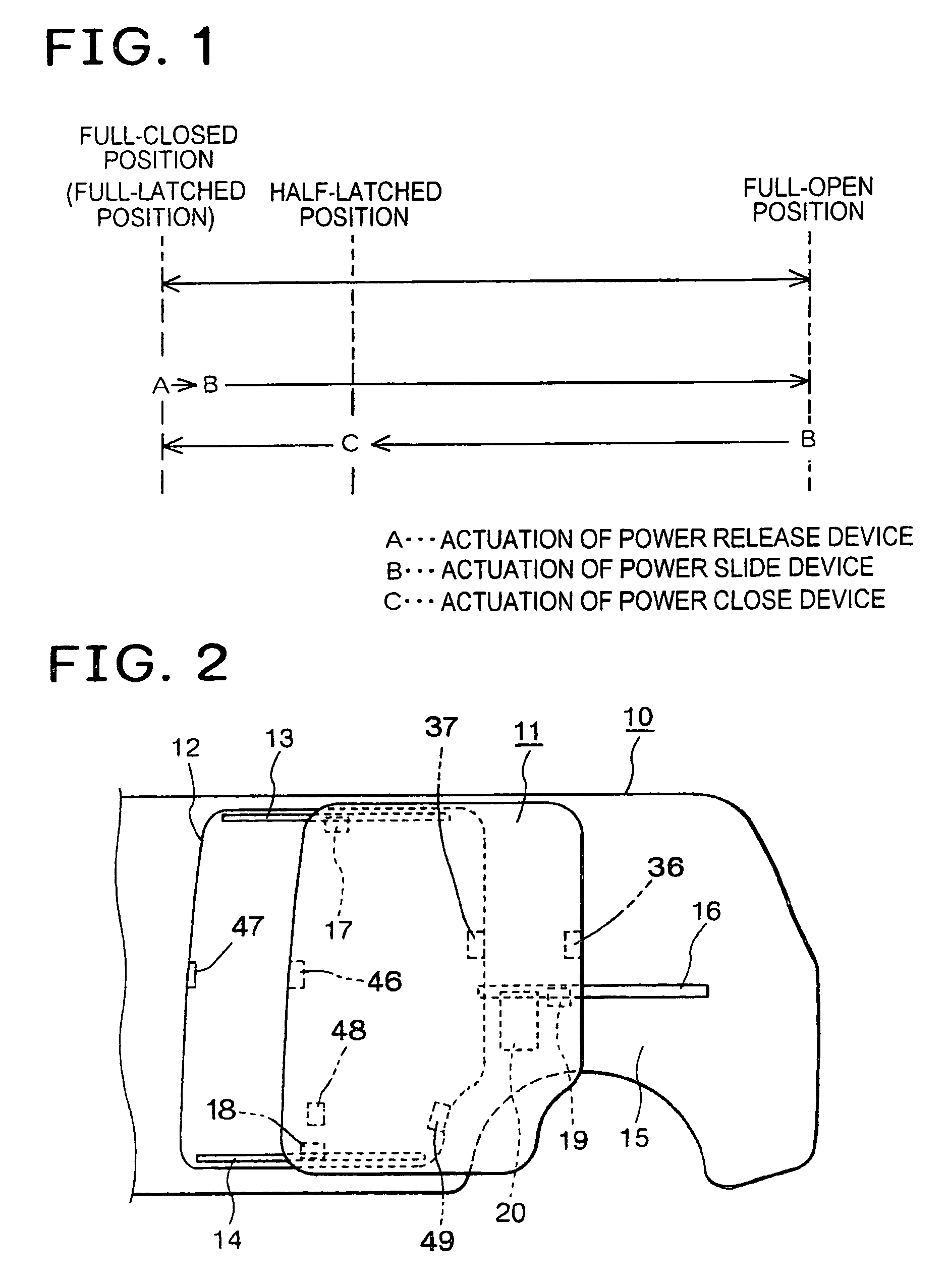
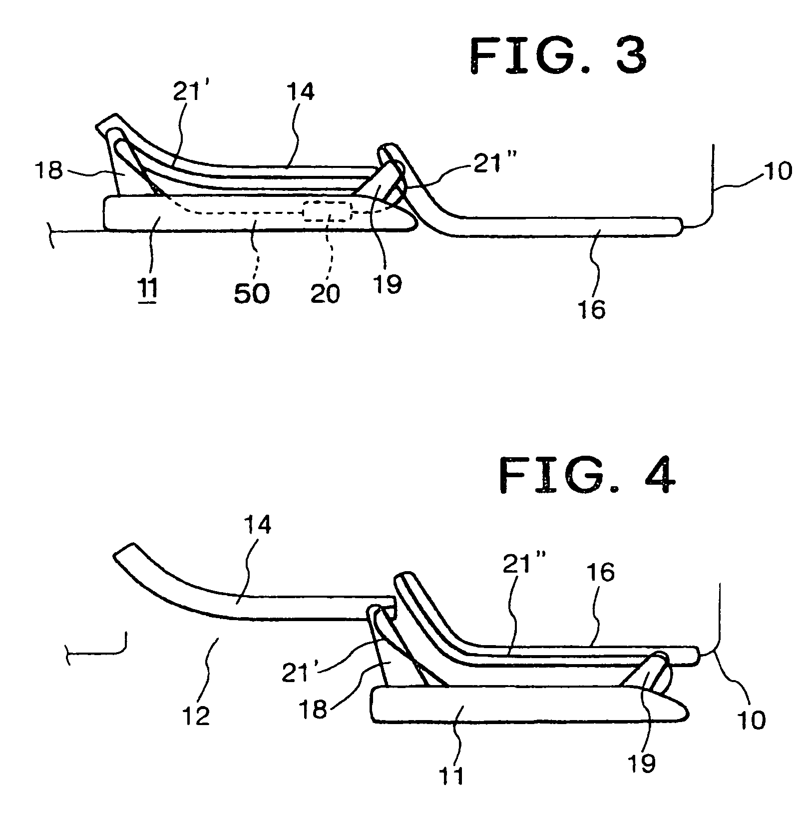
[0020]An embodiment of the present invention will be explained. FIG. 2 shows a vehicle body 10, a sliding door 11 slidably attached to the vehicle body 10, and a door ingress / egress aperture 12 that can be closed by the sliding door 11. An upper rail 13 is fixed to the vehicle body 10 in the vicinity of an upper portion of the door aperture 12, a lower rail 14 is fixed to the vehicle body 10 in the vicinity of a lower portion of the door aperture 12, and a center rail 16 is fixed to a quarter panel 15 that is a rear side surface of the vehicle body 10. The sliding door 11 is provided with an upper bracket 17 which is slidably engaged with the upper rail 13, a lower bracket 18 which is slidably engaged with the lower rail 14, and a center bracket 19 which is slidably engaged with the center rail 16. It is preferable that the respective brackets 17, 18, and 19 be pivotally mounted on the sliding door 11 so that they are free to swing, and the sliding door 11 is slidable in a door-open...


PUM


Abstract

A cylindrical worm 25 is attached to an output shaft of a motor, a first worm wheel 26 and a second worm wheel 27 are disposed on both the sides of the axial center of the cylindrical worm 25, the first worm wheel 26 and a wire drum are supported by a first support shaft 28, and the second worm wheel 27 and a swing arm are supported by a second support shaft 32. A first clutch is interposed between the first worm wheel 26 and the wire drum, a second clutch is interposed between the second worm wheel 27 and the swing arm, and the swing arm and the wire drum are rotated by controlling the first and second clutches with the motor rotating continuously.

Description

FIELD OF THE INVENTION[0001]The present invention relates to a power device for a vehicle sliding door, and more particularly, to a power device for sliding a door and releasing the door from a latched state.DESCRIPTION OF THE RELATED ART[0002]Conventional vehicle sliding doors may be concurrently provided with a power slide device for sliding a sliding door in a door-opening direction and in a door-closing direction by motor power, a power close device for moving the sliding door located at a half-latched position to a full-latched position by motor power, a power release device for unlatching a door latch unit of the sliding door by motor power, and the like.[0003]FIG. 1 shows a relation among three power devices used between a full-closed position and a full-open position of a sliding door, wherein when the sliding door is to be opened, first, a door latch unit of the sliding door is released (unlatched) by a power release device, and thereafter the sliding door is slid to a full...

Claims


Application Information

Patent Timeline
Patent Type & Authority Patents(United States)
IPC IPC(8): E05F11/00B60J5/06E05B79/20E05B81/14E05B81/20E05B81/46E05B83/40E05B85/24E05F15/603
CPCE05F15/603E05Y2201/22E05Y2201/434E05Y2201/462E05Y2800/11E05F15/646E05Y2600/41E05Y2600/46E05Y2900/531
Inventor YOKOMORI, KAZUHITO
Owner MITSUI KINZOKU ACT
Why Eureka
Try Eureka