Monitoring method and an optoelectronic sensor
- Summary
- Abstract
- Description
- Claims
- Application Information
AI Technical Summary
Benefits of technology
Problems solved by technology
Method used
Image

Examples
Embodiment Construction
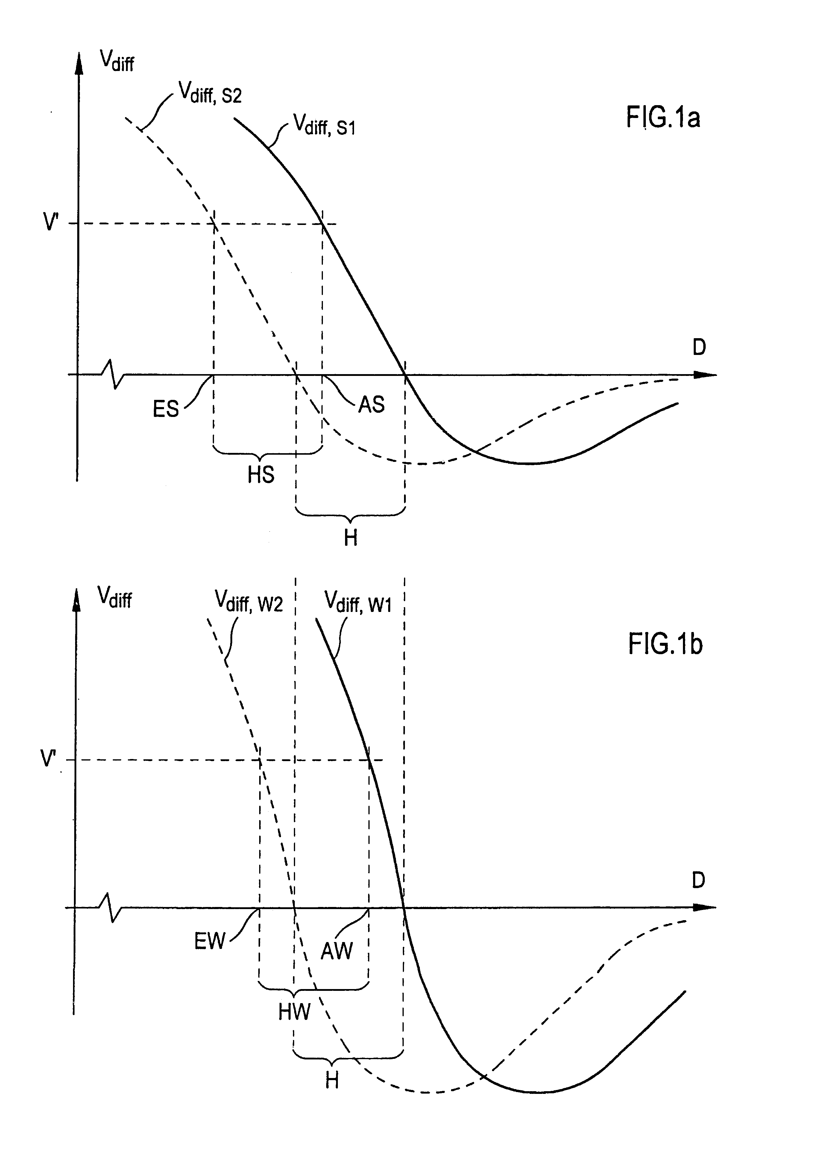
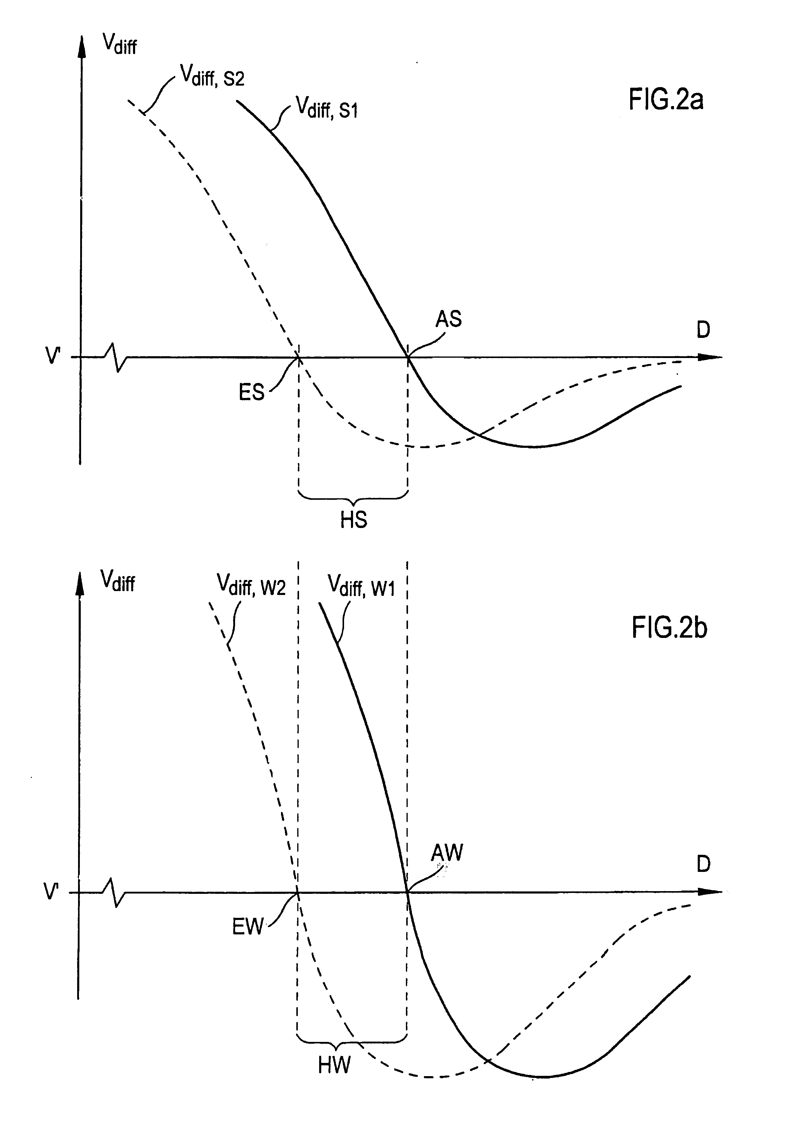
[0033]FIG. 7 illustrates the problems of a different path hysteresis for objects of different reflectance. The differential signal Vdiff is entered over the scanning distance D, and indeed for a black object S and a white object W. The differential signal Vdiff has different values, and also different gradients, for different scanning distances D due to the different reflectance of the two objects W, S. The two signal profiles only intersect at the respective zero passage.
[0034]A lower and an upper differential threshold V0′ or V1′ are shown for the example of a foreground reflection light sensor, that is, for a background masking. If an object sufficiently approaches the sensor and if the respective differential signal Vdiff exceeds the upper differential threshold V1′, a positive object detection signal is produced (switch-on distance ES or EW respectively). Only if subsequently the respective differential signal Vdiff again falls below the lower differential threshold V0′, does a...
PUM
 Abstract
Description
Claims
Application Information