Torque reaction control jig
- Summary
- Abstract
- Description
- Claims
- Application Information
AI Technical Summary
Benefits of technology
Problems solved by technology
Method used
Image
Examples
Embodiment Construction
[0017]In the following description, the various sides and surfaces of the alignment jig of the present invention are described as they are presented in the drawings. Accordingly, the use of the directional references (i.e., upper, lower, lateral side, etc.,) is only to be construed as they relate to the orientation of the jig in the drawings. Insofar as the jig is capable of use in various orientations, these directional references are not to be construed in a limiting fashion.
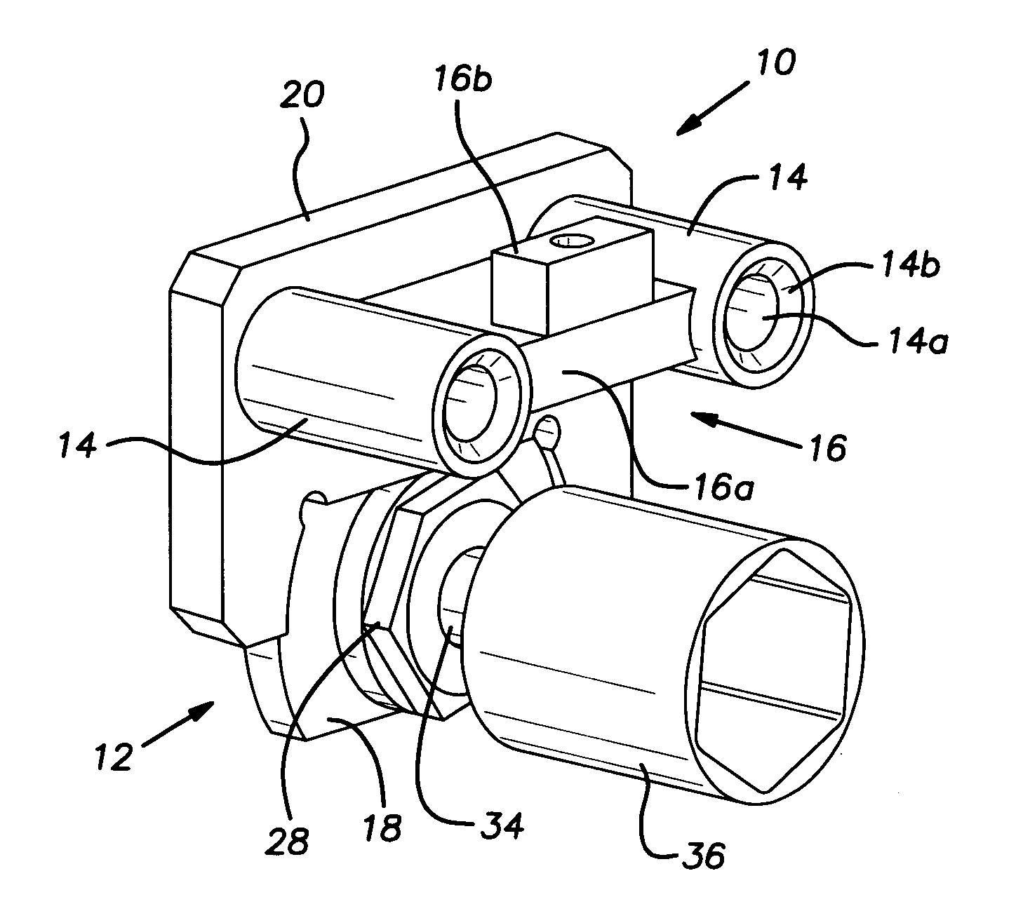
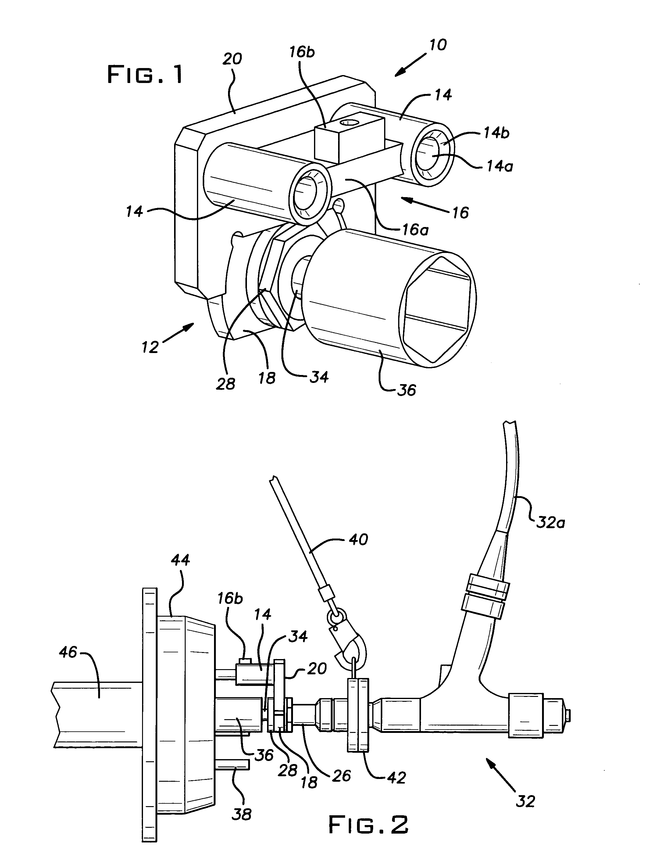
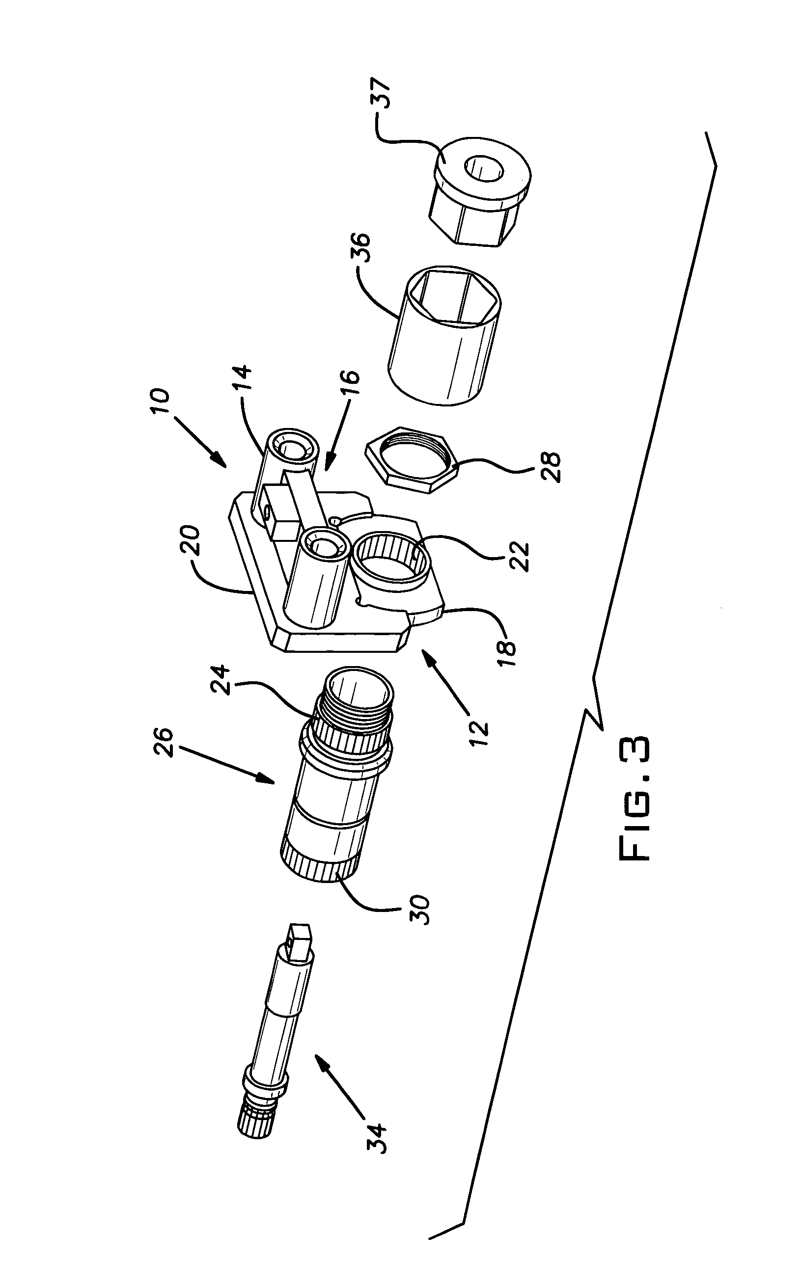
[0018]With reference to FIGS. 1–3, the torque reaction control jig 10 of the present invention includes a jig body 12, a pair of wheel stud receptacles or nests 14, and a barrier member 16. In the preferred and illustrated embodiment, the jig body 12 includes an adaptor body 18 that is affixed to an alignment body 20.
[0019]The adaptor body 18 has a generally rectangular peripheral shape, albeit with curved or arcuate lateral sides, and is partially received within a similarly shaped, downwardly facing recess f...
PUM
 Abstract
Description
Claims
Application Information
 - R&D
- Intellectual Property
- Life Sciences
- Materials
- Tech Scout
- Unparalleled Data Quality
- Higher Quality Content
- 60% Fewer Hallucinations
Browse by: Latest US Patents, China's latest patents, Technical Efficacy Thesaurus, Application Domain, Technology Topic, Popular Technical Reports.
© 2025 PatSnap. All rights reserved.Legal|Privacy policy|Modern Slavery Act Transparency Statement|Sitemap|About US| Contact US: help@patsnap.com


