Actuator provided with locking mechanism

a technology of locking mechanism and actuator, which is applied in the direction of vehicular safety arrangement, transportation and packaging, pedestrian/occupant safety arrangement, etc., can solve the problems of inability to hold the sheet tip portion in the lifted state, the gap between the hood and each device in the engine room, and the input load increas

Inactive Publication Date: 2006-03-21
NHK SPRING CO LTD
View PDF10 Cites 12 Cited by
  • Summary
  • Abstract
  • Description
  • Claims
  • Application Information

AI Technical Summary

Benefits of technology

[0012]An object of the present invention is to provide an actuator in which relative movement of a piston rod with respect to a cylinder

Problems solved by technology

When the submarine phenomenon occurs, crew's buttocks or lower limbs move forwards/downwards, and there is a possibility of secondary collision of the lower limbs with an instrument panel before the crew.
That is, when the hood is pushed upwards, a gap is made between the hood and each device in an engine room.
However, when t

Method used


Image

  • Actuator provided with locking mechanism
  • Actuator provided with locking mechanism
  • Actuator provided with locking mechanism

Examples


first embodiment

[0035]the present invention will be described hereinafter with reference to FIGS. 1 to 8.

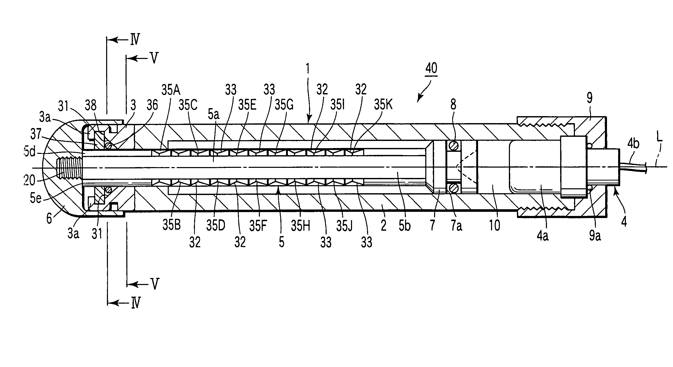
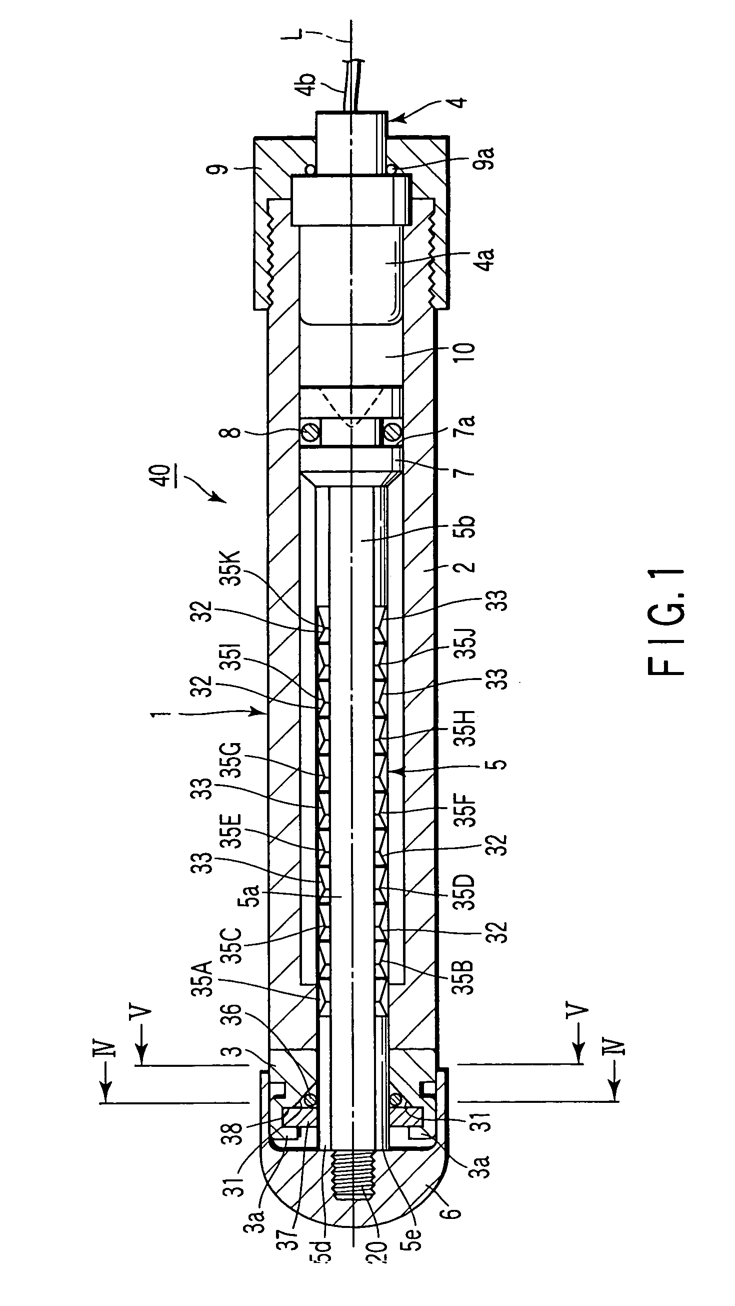
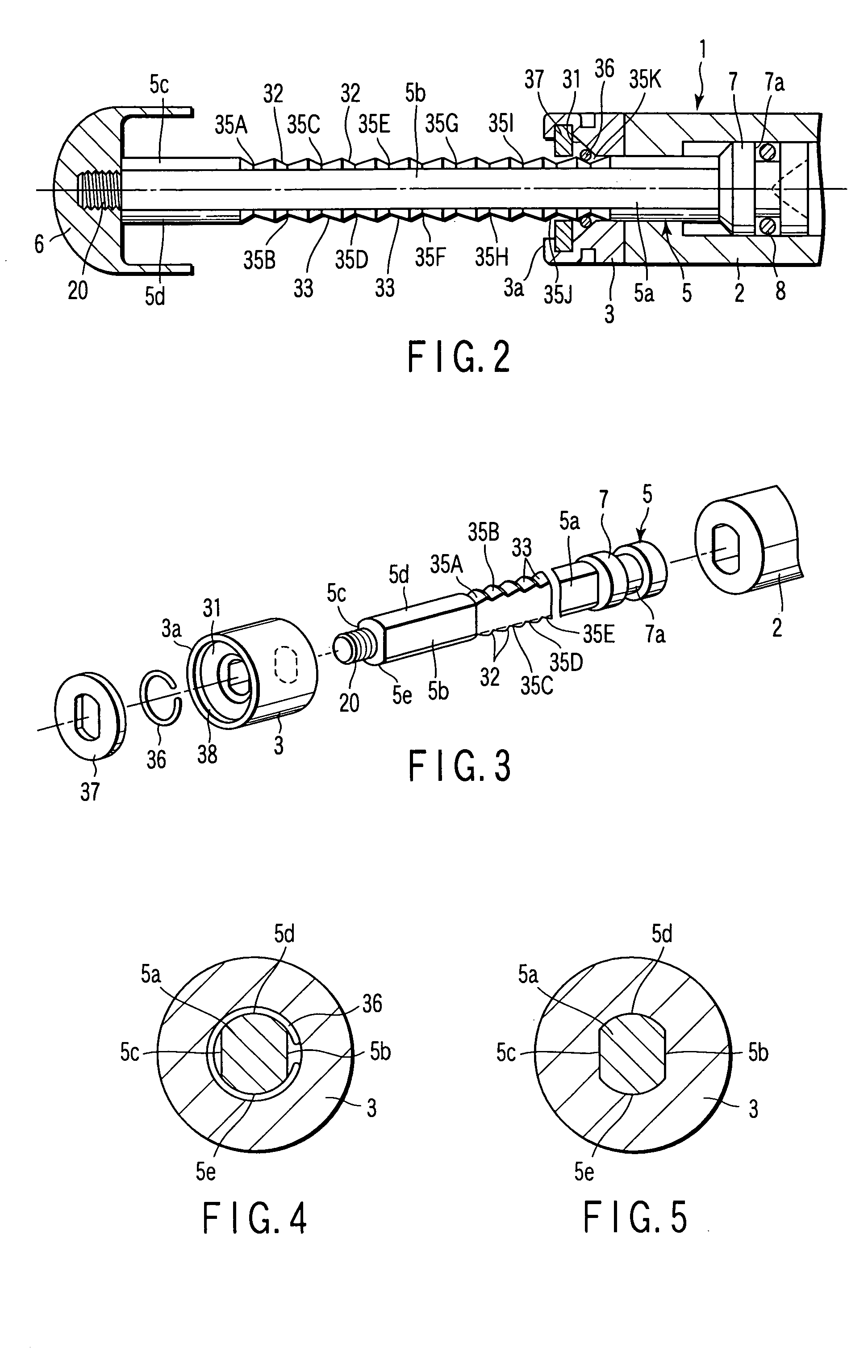
[0036]As shown in FIG. 1, an actuator 40 of the first embodiment comprises a hollow cylinder 1 including a hollow casing 3, a gas generation device 4 which is a power generation device, a piston rod 5 including a tip cap 6, a piston 7 and the like. As shown in FIG. 2, the actuator 40 is constituted in such a manner that the front end of the piston rod 5 protrudes from the front end of the cylinder 1 by ignition of the gas generation device 4.

[0037]In detail, the cylinder 1 includes a cylinder main body 2 and the casing 3 disposed in a front end portion of the cylinder main body 2. The gas generation device 4 is disposed in a rear end portion of the cylinder main body 2. The gas generation device 4 includes a gas generation section 4a in which gunpowder for generating gas is stored, and a lead wire 4b for igniting a gas generation body (not shown) stored in the gas generation section 4a extends f...

second embodiment

[0070]the present invention will be described hereinafter with reference to FIG. 9.

[0071]In this embodiment, an inclined portion 37a inclined rearwards / inwards from a front outer side is disposed on an inner edge of the stopper member 37. For example, the stopper member 37 can be bent to form the inclined portion 37a integrally. It is to be noted that the other constitution is the same as that of the first embodiment including not-shown parts, and is therefore denoted with the same reference numerals in the drawing to omit redundant description.

[0072]The piston rod 5 is protruded from the front end of the cylinder 1 as smoothly as possible in the actuator 40 applied to a hood device 70, seat device 80 or the like described later. For this purpose, the C ring 36 needs to enlarge its diameter and to ride over each protruding portion 39 as smoothly as possible.

[0073]According to the embodiment, when the pressure in the gas chamber 10 rises, and the piston 7 moves in a forward protrudin...

third embodiment

[0078]the present invention will be described hereinafter with reference to FIG. 10.

[0079]In the embodiment, the cylinder 1 in which the cylinder main body 2 is integrated with the casing 3 is used. It is to be noted that the other constitution is the same as that of the first embodiment including the not-shown parts, and is therefore denoted with the same reference numerals in the drawing to omit the redundant description.

[0080]According to the embodiment, since the cylinder main body 2 is integrated with the casing 3, members constituting the actuator can be reduced.


PUM


Abstract

A piston rod is formed in a diameter smaller than an inner diameter of a hollow cylinder. The piston rod is inserted in the cylinder so as to be relatively movable in an axial direction of the cylinder. A locking mechanism comprises a first surface provided on the inner surface of the cylinder, a plurality of second surfaces arranged in an axial direction of the piston rod and parallel to one another, and a locking member. The first surface is so inclined that the inside diameter of the cylinder gradually increases toward one end of the cylinder. Each second surface is so inclined that the diameter of the piston rod gradually increases to the one end of the piston rod. The locking member is held between the first surface and any one of the second surfaces to lock relative movement of the piston rod with respect to the cylinder.

Description

CROSS-REFERENCE TO RELATED APPLICATIONS[0001]This application is based upon and claims the benefit of priority from prior Japanese Patent Application No. 2003-117326, filed Apr. 22, 2003, the entire contents of which are incorporated herein by reference.BACKGROUND OF THE INVENTION[0002]1. Field of the Invention[0003]The present invention relates to an actuator for use, for example, in a vehicle, particularly to an actuator provided with a locking mechanism capable of locking a piston rod with respect to a cylinder.[0004]2. Description of the Related Art[0005]An actuator is disposed, for example, in a safety device disposed in a vehicle in order to enhance safety of crews at the time of collision. The actuator is also disposed in the safety device or the like disposed in the vehicle in order to relax an impact applied to a pedestrian in a case where the vehicle collides with the pedestrian.[0006]For example, when a seat belt is not attached to the crew in a normal state at the time o...

Claims


Application Information

Patent Timeline
IPC IPC(8): F15B15/26B60R21/34B60N2/427B60R21/38F15B15/19
CPCB60N2/42763F15B15/261F15B15/19B60R21/38
Inventor YAMAGUCHI, HIROYOSHI
Owner NHK SPRING CO LTD
Why Eureka
Try Eureka