Extendable remote motored sander and method therefor

Inactive Publication Date: 2006-03-21
BIRK JOHN
View PDF6 Cites 30 Cited by
  • Summary
  • Abstract
  • Description
  • Claims
  • Application Information

AI Technical Summary

Benefits of technology

[0010]It is still another object of the present invention to provide an improved sander that is extendable in order to reach high places such as ceilings.
[0011

Problems solved by technology

Sanding by hand is a tedious and time consuming endeavor which requires a person to expend a lot of energy by manually moving the sander.
However, power sanders are heavier than hand sanders and are difficult to hold above one's head for extend periods of time.
However, it has been f

Method used


Image

  • Extendable remote motored sander and method therefor
  • Extendable remote motored sander and method therefor
  • Extendable remote motored sander and method therefor

Examples


Embodiment Construction

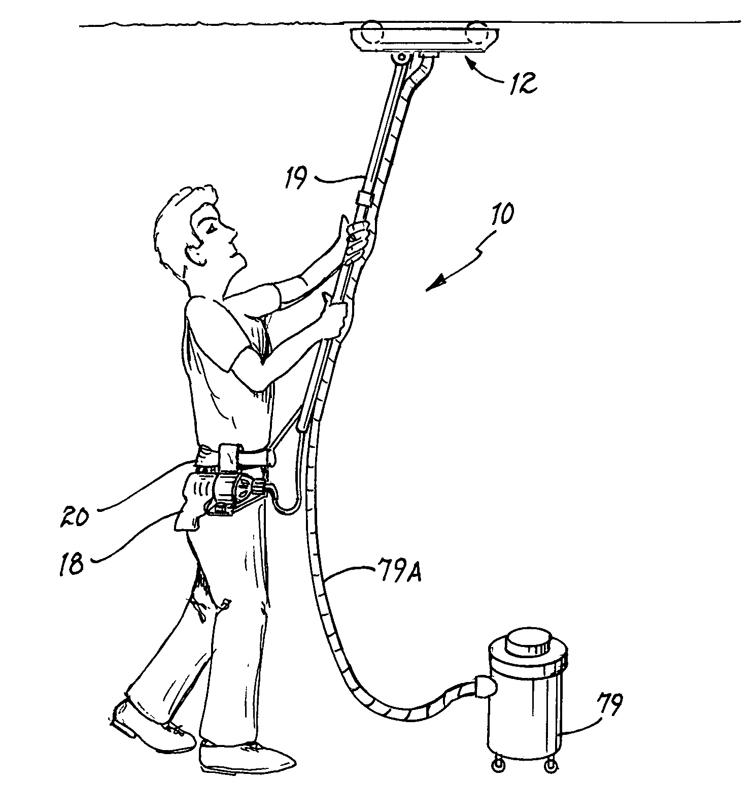
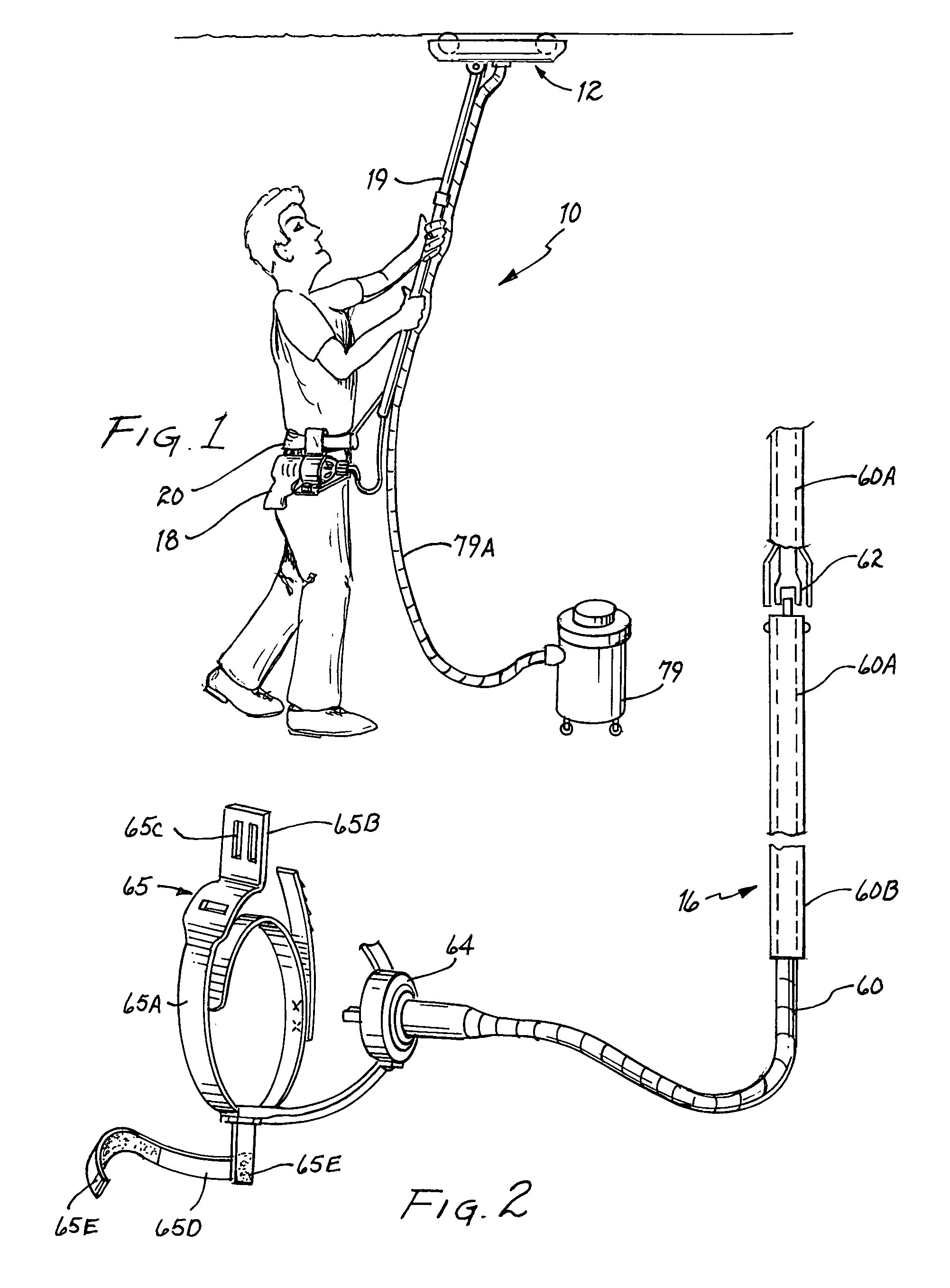
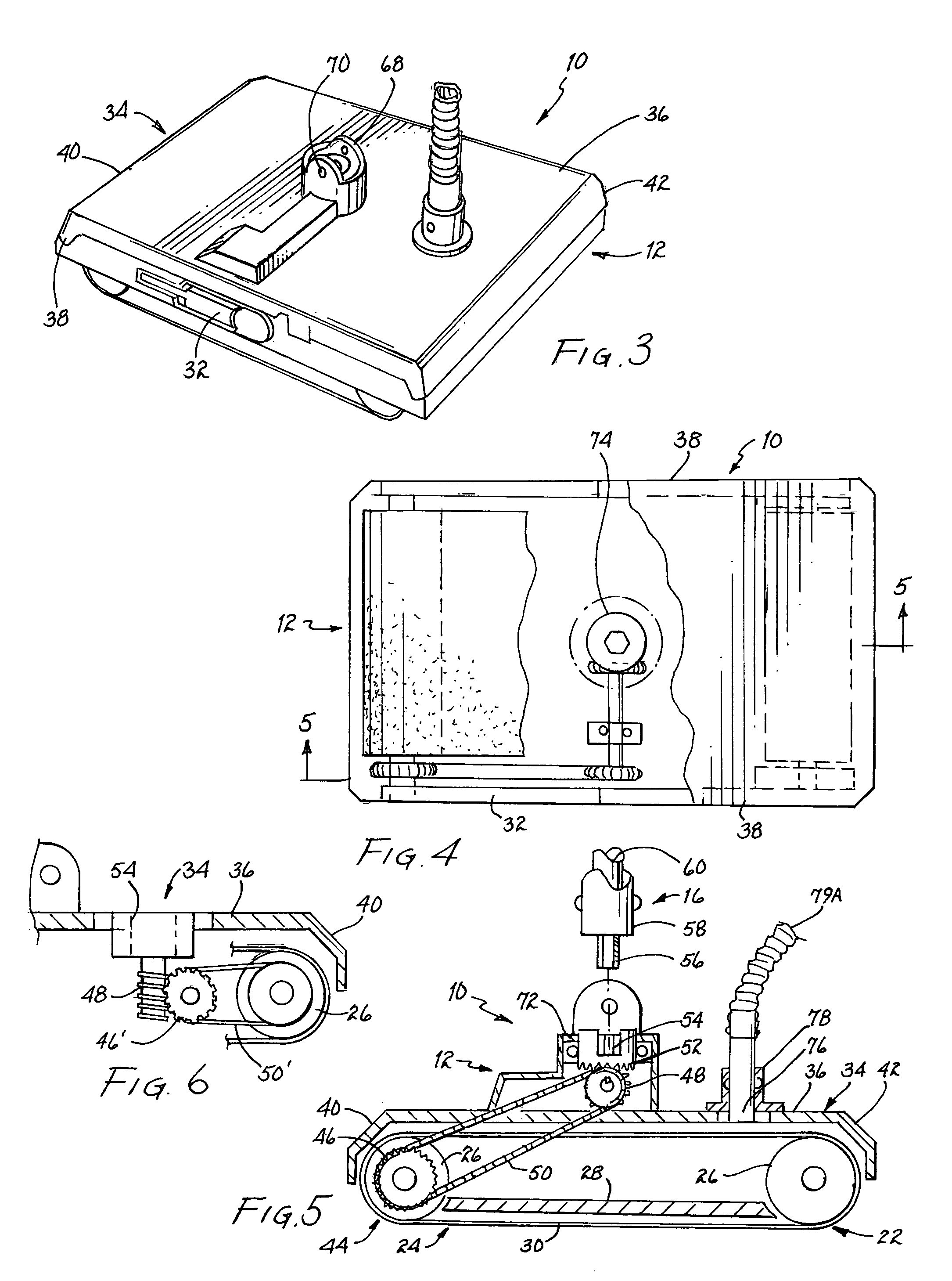
[0012]In accordance with one embodiment of the present invention, a remote powered extendable sander is disclosed. The remote powered extendable sander has a sanding unit. The sanding unit has a belt plate. A pair of rollers are provided wherein a first roller is placed on a front side of the belt plate and a second roller is placed on a rear side of the belt plate. A sandpaper belt is placed around the pair of rollers and a bottom surface of the belt plate so the bottom surface of the belt plate forms a sanding surface for the sanding unit. A drive system is coupled to at least one of the pair of rollers. The drive system is used to rotate the pair of rollers to move the sandpaper belt. A drive unit is used for powering the sanding unit. The drive unit is a small motorized construction tool. The drive unit being located away from the sanding unit and removably coupled to an individual using the remote powered extendable sander. A drive transfer unit is coupled to the drive system f...


PUM


Abstract

A remote powered extendable sander has a sanding unit having a sanding surface. A drive system is coupled to the sanding unit. The drive system is used to move the sanding surface. A drive transfer unit is provided for transferring rotational motion from a small motorized construction tool to the drive system for powering the sanding unit. A housing is coupled to the sanding unit. An extension member is removably coupled to the housing for raising the remote powered extendable sander.

Description

BACKGROUND OF THE INVENTION[0001]1. Field of the Invention[0002]This invention relates generally to construction tools, and more specifically, to an extendable sander which is able to reach high places such as ceiling and which is remotely powered by a standard power tool device thereby lighten the weight of the extendable sander so that a person can more easily use the sander.[0003]2. Description of the Prior Art[0004]Presently, when sanding high out of reach areas such as a ceiling or the like, one has to use stilts or erect scaffolding. Sanding of a ceiling is generally necessary during construction due to the use of joint compound, sometimes called mud, used to cover nail heads driven into drywall and to cover tape which applied to drywall joints. Sanding is generally done by using a hand sander or a powered drywall sander. Sanding by hand is a tedious and time consuming endeavor which requires a person to expend a lot of energy by manually moving the sander. Because of this, ma...

Claims


Application Information

Patent Timeline
IPC IPC(8): B24B23/00
CPCB24B23/02B24B7/188
Inventor BIRK, JOHN
Owner BIRK JOHN
Why Eureka
Try Eureka