Network conferencing system, equipment management method and data presentation method

a network conferencing and equipment management technology, applied in the field of network conferencing systems, equipment management methods and data presentation methods, can solve the problems of troublesome presenters, no function of conventional conferencing systems to integrate manage electronic equipment used for conferences

Inactive Publication Date: 2006-03-21
SONY CORP
View PDF5 Cites 104 Cited by
  • Summary
  • Abstract
  • Description
  • Claims
  • Application Information

AI Technical Summary

Benefits of technology

[0010]According to the present invention, there is provided a network conferencing system in which an output electronic equipment for presenting the contents of presentation, a generating electronic equipment for generating the contents of presentation to be presented by the output electronic equipment, a plurality of attendant electronic equipments operated by users attending a conference, and a conference management server connected with the output electronic equipment and the attendant electronic equipments so as to transmit and receive information to and from the output electronic equipment and the attendant electronic equipments, are connected via a communication network. In the network conferencing system, each of the attendant electronic equipments has an information input/output function for inputting and outputting information from and to the other attendant electronic equipments and the output electronic equipment via the communication network, a presentation function for presenting the contents of presentation by using the output electronic equipment, a presentation contents browsing function for

Problems solved by technology

In the foregoing conferencing system, however, applications corresponding only to the attendant terminals and the presenter terminal exist as the provided applications despite the actual presence of the chairman, and no application is provided for carrying out the processing proper to the chairman.
However, the conventional conferencing syste

Method used


Image

  • Network conferencing system, equipment management method and data presentation method
  • Network conferencing system, equipment management method and data presentation method
  • Network conferencing system, equipment management method and data presentation method

Examples


Embodiment Construction

[0076]A preferred embodiment of the present invention will now be described in detail with reference to the drawings.

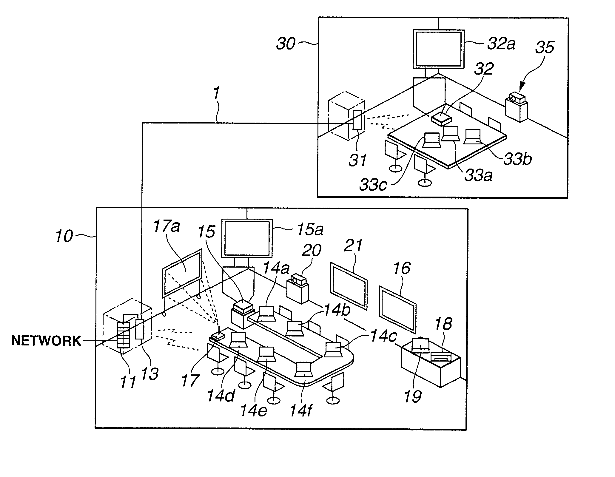
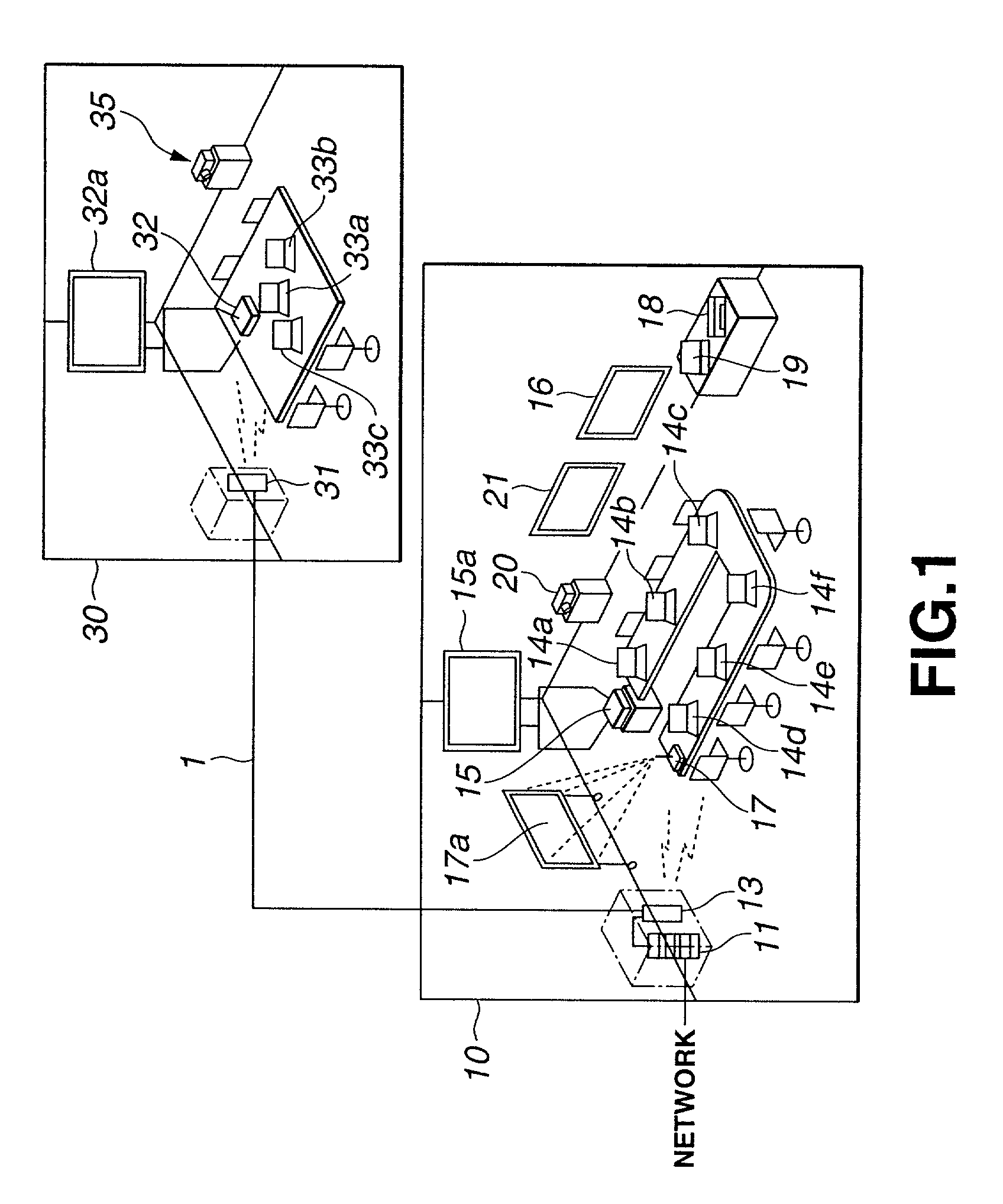
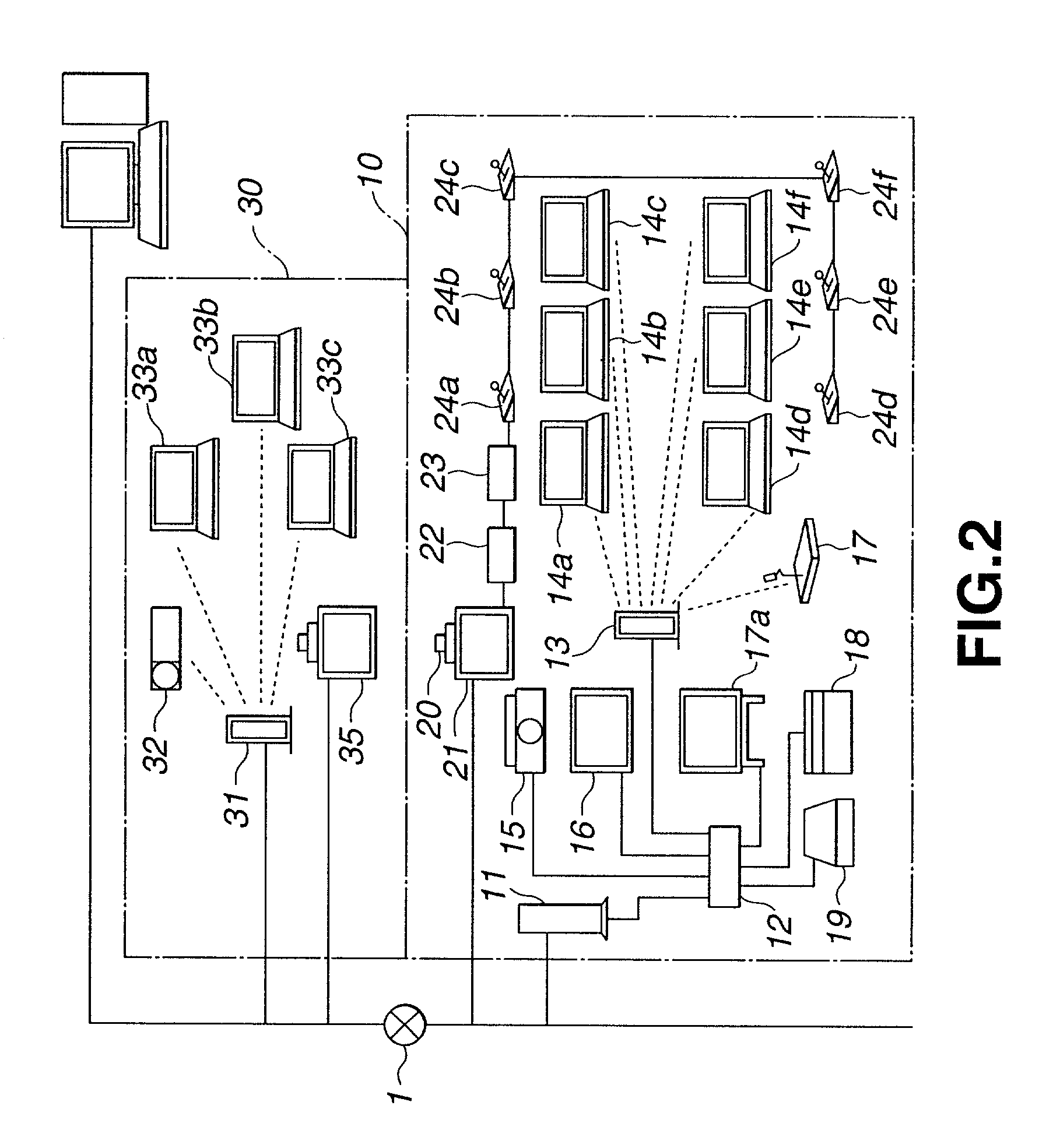
[0077]The present invention is applied to a network conferencing system as shown in FIGS. 1 and 2.

[0078]This network conferencing system is constituted by a first conference room 10 and a second conference room 30. The first conference room 10 and the second conference room 30 are connected with each other via a communication network 1. In this network conferencing system, the first conference room 10 and the second conference room 30 are connected by the communication network 1 for transmitting data and various types of information via a communication channel in accordance with, for example, a wired LAN protocol (e.g., Ethernet).

[0079]In the network conferencing system, a plurality of client PCs operated by attendants at a conference are provided. The authority to be a chairman and the authority to be a presenter are given to any of the client PCs and the authority t...


PUM


Abstract

Various electronic equipments used in a network conferencing system are integrally managed and presentation is made in a simple manner. When each attendant electronic equipment becomes a chairman terminal having an equipment management function, it inquires the availability of an electronic equipment used for a conference, then obtains information related to an available equipment from a client control section of a conference management server, and determines whether the electronic equipment used for the conference is an output electronic equipment such as a projector or a generating electronic equipment such as a scanner. Thus, an icon display of the generating electronic equipment and an icon display of the output electronic equipment are provided while separating an area for the icon display of the generating electronic equipment and an area for the icon display of the output electronic equipment, by the display function of each attendant electronic equipment.

Description

CROSS-REFERENCE TO RELATED APPLICATIONS[0001]This is a continuation of International Application PCT / JP01 / 03913, with an international filing date of May 10, 2001, which was not published under English under PCT Article 21(2).TECHNICAL FIELD[0002]This invention relates to a network conferencing system for connecting a plurality of electronic equipments and conferencing equipments via a network so that a conference is realized by attendants operating respective electronic equipments. This invention also relates to a network conferencing system and equipment management method, and a conference management server and equipment management method, adapted for managing an electronic equipment such as a projector device used for a conference. This invention also relates to a network conferencing system and data presentation method, and a conference management server and data presentation method, adapted for making presentation by a simple technique.BACKGROUND ART[0003]There has been known a...

Claims


Application Information

Patent Timeline
IPC IPC(8): G06F15/16G06F3/033H04L12/18H04L29/06H04L29/08
CPCG06F3/033H04L12/1822H04L12/1831H04L65/403H04L67/36H04L29/06H04L69/329H04L29/06027H04L67/75H04L12/18H04L9/40H04L65/1101
Inventor LEE, SEIKEIFUJIYAMA, HIDEHARUKURASHIGE, SHUJIYAMAGUCHI, MASATAROMIYAKE, TORU
Owner SONY CORP
Why Eureka
Try Eureka