Luminaire having symmetrically opposed asymmetrical reflectors

a technology of symmetrical opposing and asymmetric reflectors, which is applied in the field of luminaires, can solve the problems of not being optimized for any particular application, the light pattern emitted is not particularly efficient, and the luminaire is long and narrow, so as to minimize internal reflection, widen the light distribution pattern, and reduce the effect of internal reflection

Inactive Publication Date: 2006-04-18
LSI INDS
View PDF18 Cites 11 Cited by
  • Summary
  • Abstract
  • Description
  • Claims
  • Application Information

AI Technical Summary

Benefits of technology

[0009]The present invention is a luminaire which overcomes wide angle lighting drawbacks associated with the currently existing luminaires. More specifically, the luminaire comprises a housing in which multiple lamps are each disposed within their own reflectors and the reflectors have at least a pair of asymmetric reflectors that are disposed symmetrically relative to each other. This permits the middle lamps and reflectors, if used, to provide a standard light distribution pattern, while the outer asymmetric pairs are used to provide a wider angle of illumination and increased vertical foot candles.
[0010]In the preferred embodiment, the luminaire has three lamps and reflectors, including one symmetrical reflector in the center and two asymmetrical reflectors on the sides. The center lamp and reflector provides a standard light distribution pattern that is focused on the horizontal space below the luminaire, while the two side lamps and reflectors are principally responsible for providing the increased wide angle illumination and vertical.
[0014]By virtue of the foregoing, there is thus provided a luminaire that provides increased vertical foot candles and a widespread light distribution pattern. Additionally, the design of the reflectors provides a high efficiency as the result of the minimized internal reflections, thereby providing greater illumination and permitting the use of lower wattage lamps, thereby reducing usage of electricity while preserving usable light output. Further, the luminaire permits use of a single luminaire type for varying applications without requiring reflector adjustments.

Problems solved by technology

As the fluorescent tubes are usually long and narrow, these luminaires also tend to be long and narrow.
A drawback associated with such symmetrical luminaires is that the reflector is not particularly efficient because of internal reflections, the resulting light distribution pattern has low vertical foot-candles and the light pattern emitted is not optimized for any particular application.
The widespread light pattern increases the footprint over which light is projected and also results in increased vertical foot candles.
Also, the greater the efficiency of the luminaire the more light there is that is available for the widespread footprint, thereby resulting in increased light intensity throughout the footprint.
In each of these examples the luminaire provides increased wide angle lighting and vertical foot candles in a particular region below the luminaire, however, such increases are made at the expense of the lighting directly below the luminaire.
This however, results in a less stable luminaire that requires adjustment and costs more to manufacture because of the added complexity of having moving parts.
Further, the efficiency of such luminaires is greatly reduced either because they use materials that are flexible that are not the best possible reflectors or they use more solid reflector elements that are moved around but have spacing between the elements.

Method used


Image

  • Luminaire having symmetrically opposed asymmetrical reflectors
  • Luminaire having symmetrically opposed asymmetrical reflectors
  • Luminaire having symmetrically opposed asymmetrical reflectors

Examples


Embodiment Construction

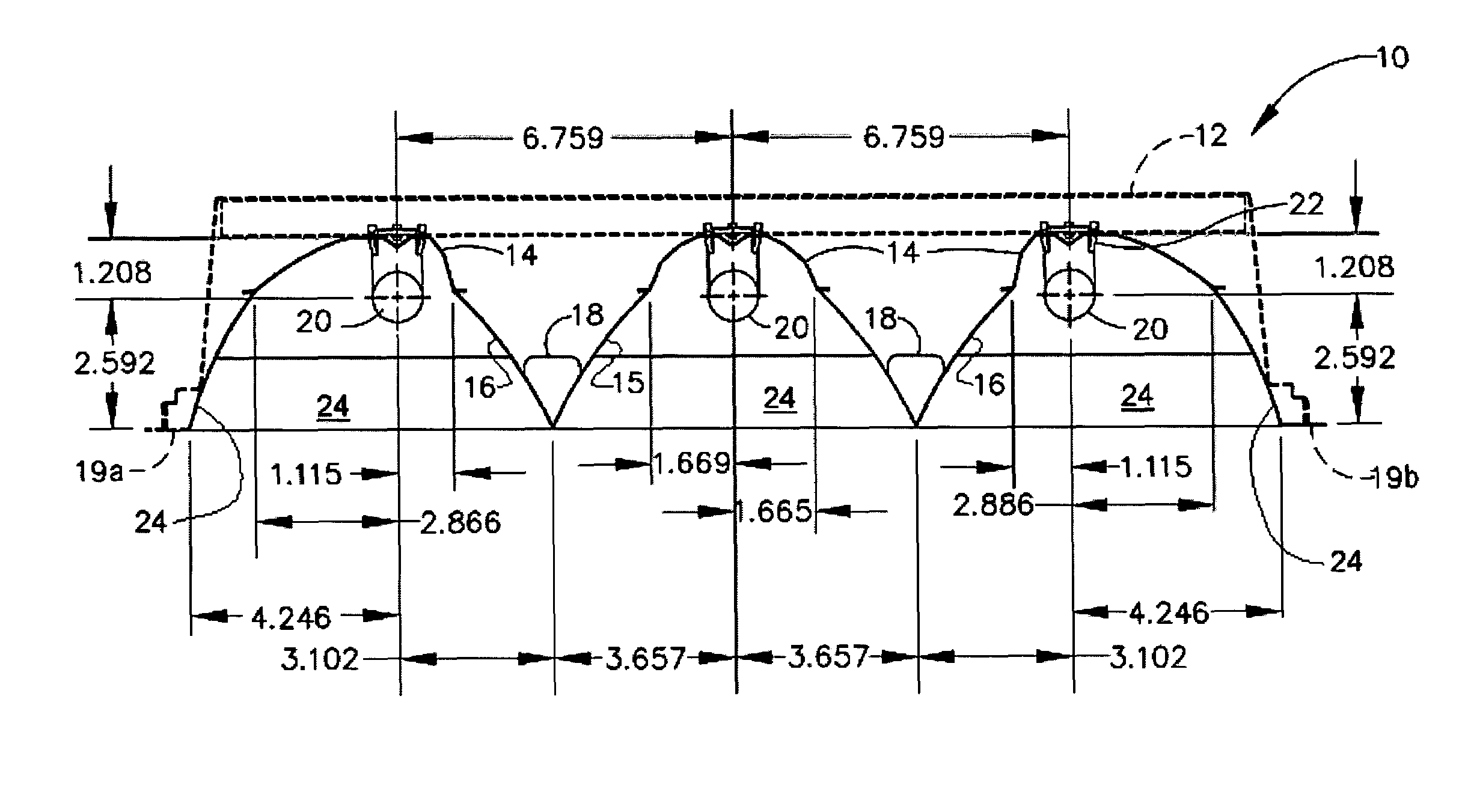
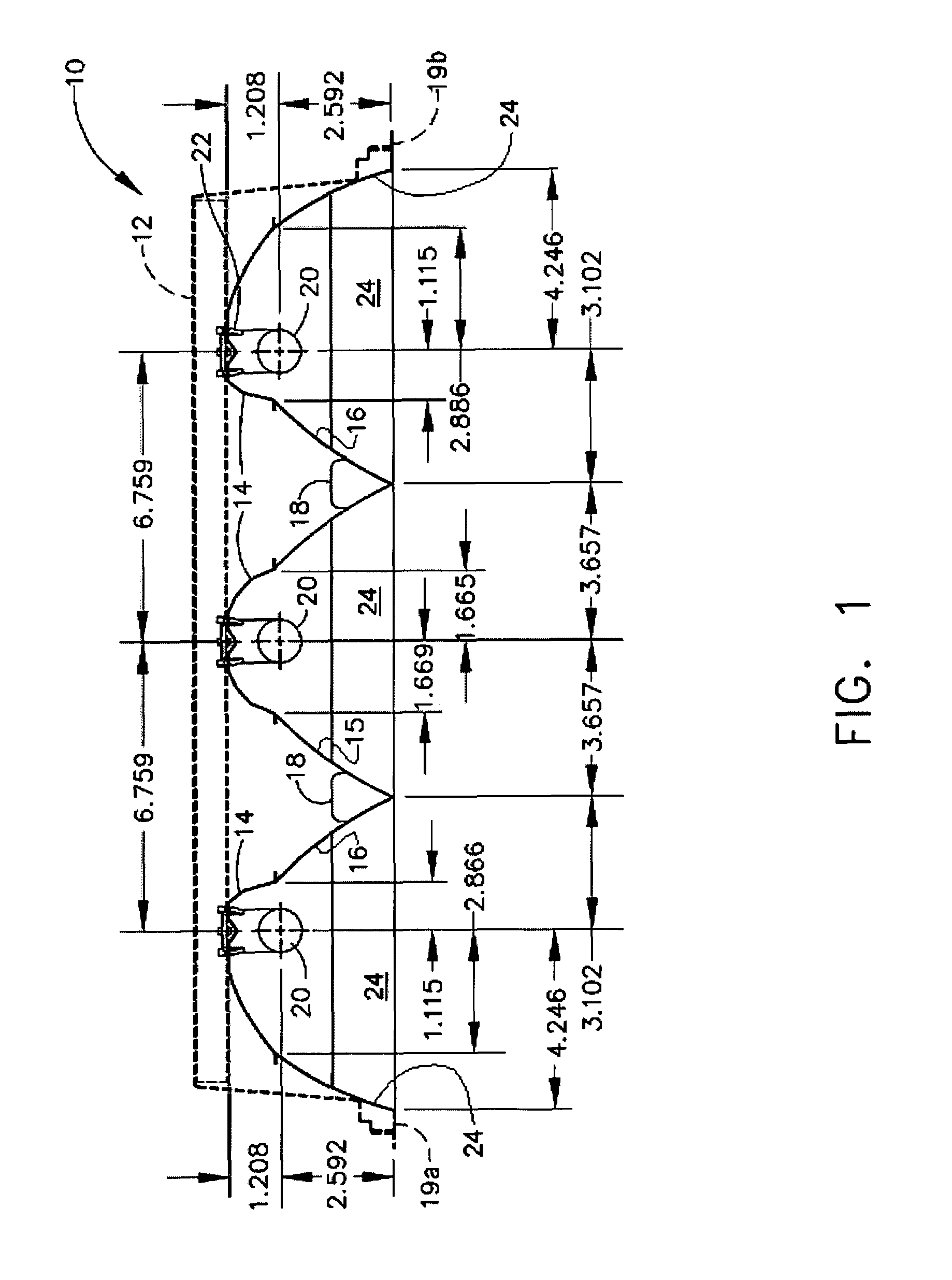
[0022]The luminaire 10, as depicted in FIGS. 1 and 5, comprises a housing 12 in which three reflectors 14 are disposed, including a center reflector 15 and side reflectors 16. While it would be possible to form the reflectors together in a single piece, it is more convenient to form them as separate reflectors. The reflectors 14 are then joined using braces 18 with any common bonding means such as adhesives, screws or locking tabs. The outer edges 19a and 19b of the side reflectors 16 are then joined to the edge of the housing 12. Within each reflector 14 volume is a lamp 20 having a base at each opposed end 21, and which is held in place at the ends 21 via a set of commonly used fluorescent tube sockets 22. The sockets are electrically connected to a power source, and have an electric contact for electrically connecting to the base of the lamps. Louvers 24, as depicted in FIG. 5, can also be attached to the luminaire 10 to provide additional direction for the light.

[0023]FIG. 1 als...


PUM


Abstract

A luminaire comprising a housing, plurality of reflectors, lamps and electrically connected lamp sockets. The luminaire has at least two asymmetrical reflectors that are symmetrically opposed to each other and ideally has at least one symmetrical reflector located between the asymmetrical reflectors.

Description

FIELD OF THE INVENTION[0001]This invention relates generally to luminaires and more particularly to luminaires using reflectors to provide widespread lighting footprint.BACKGROUND OF THE INVENTION[0002]A commonly used type of luminaire for illuminating large work areas is a reflective, fluorescent luminaire. These luminaires are typically either recessed into the ceiling or are mounted on the ceiling within a housing that contains the reflector(s) and lamps. Common applications include lighting for offices, workspaces or large retail areas.[0003]Existing fluorescent luminaires typically include a number of fluorescent lamps disposed within a housing and have reflectors placed above the lamps. Often louvers are placed below the luminaire to prevent scattering of the light and to focus the light onto the horizontal surface below. As the fluorescent tubes are usually long and narrow, these luminaires also tend to be long and narrow. The industry standard fluorescent luminaire has eight...

Claims


Application Information

Patent Timeline
Patent Type & Authority Patents(United States)
IPC IPC(8): F21V7/09F21S8/02F21S8/04F21V7/00
CPCF21S8/02F21S8/04F21V7/09F21Y2103/00F21V7/005
Inventor WHITE, BARRYPRONER, STEVE
Owner LSI INDS
Why Eureka
Try Eureka