Luminous flux control member and illumination device

a technology of luminous flux and control member, which is applied in the direction of semiconductor devices for light sources, fixed installations, lighting and heating apparatus, etc., can solve the problems of short lifespan, high temperature, and high power consumption, and achieve the effect of wide illumination angle and simple structur

Inactive Publication Date: 2015-03-17
ENPLAS CORP
View PDF12 Cites 1 Cited by
  • Summary
  • Abstract
  • Description
  • Claims
  • Application Information

AI Technical Summary

Benefits of technology

[0011]According to the present invention, it is possible to provide an illumination device, such as an LED bulb, which can broadly expand light emitted from the LED, and has a simple structure of one LED and the lenses (light flux controlling member), and a wide illumination angle.

Problems solved by technology

However, the incandescent light bulbs have disadvantages such that power consumption is high, temperature is high, and lifespan is short.
However, since the LEDs emit light only in a forward direction, when an LED bulb of the related art is attached to a ceiling, the light that is radiated to the ceiling and a wall surface decreases.

Method used


Image

  • Luminous flux control member and illumination device
  • Luminous flux control member and illumination device
  • Luminous flux control member and illumination device

Examples


Embodiment Construction

[0032]Hereinafter, embodiments of the present invention will be described in detail with reference to the drawings. In the following description, an LED bulb that has an LED as a light-emitting element will be described as a representative example of an illumination device of the present invention.

[0033](Configuration of LED Bulb)

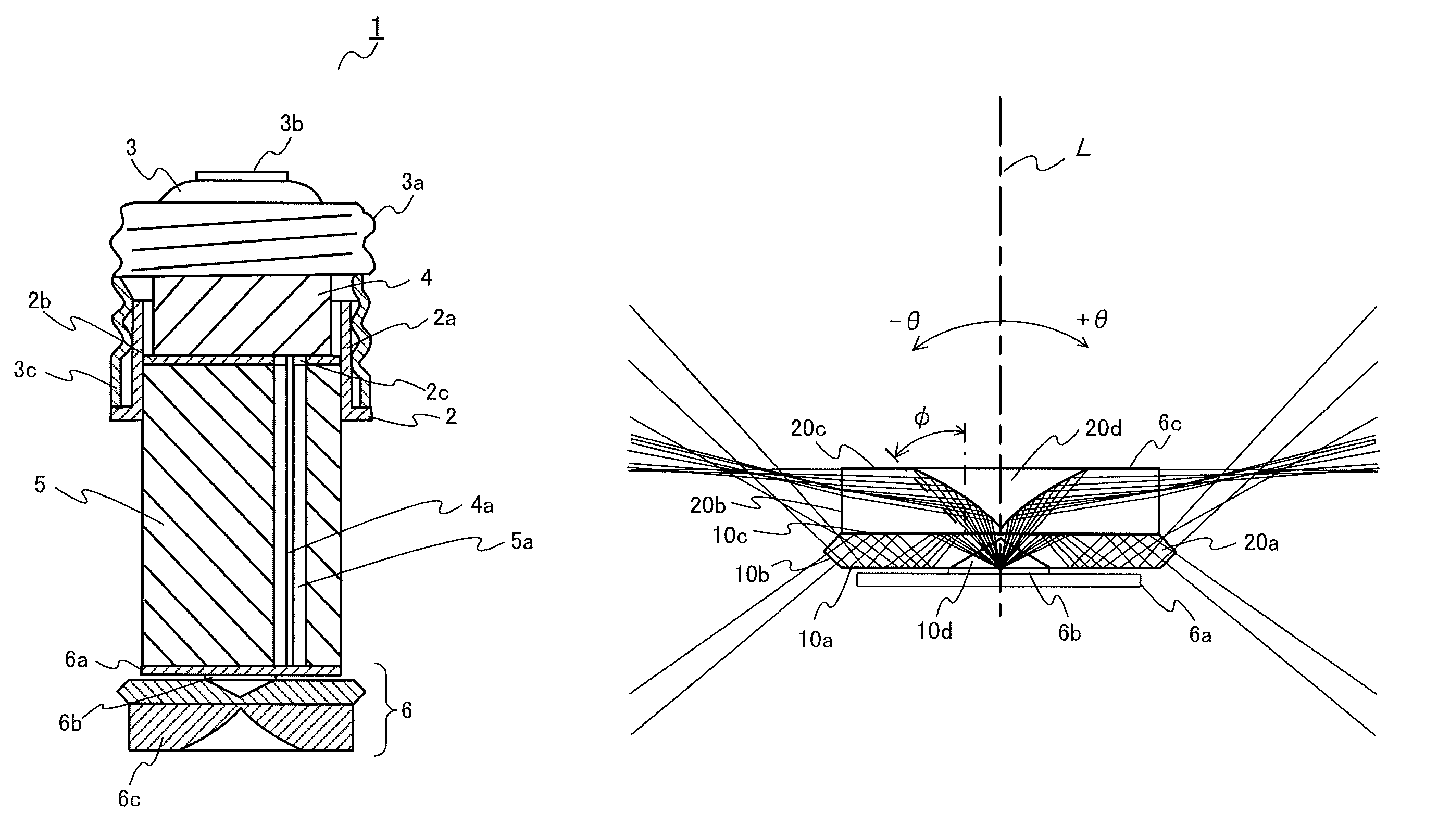
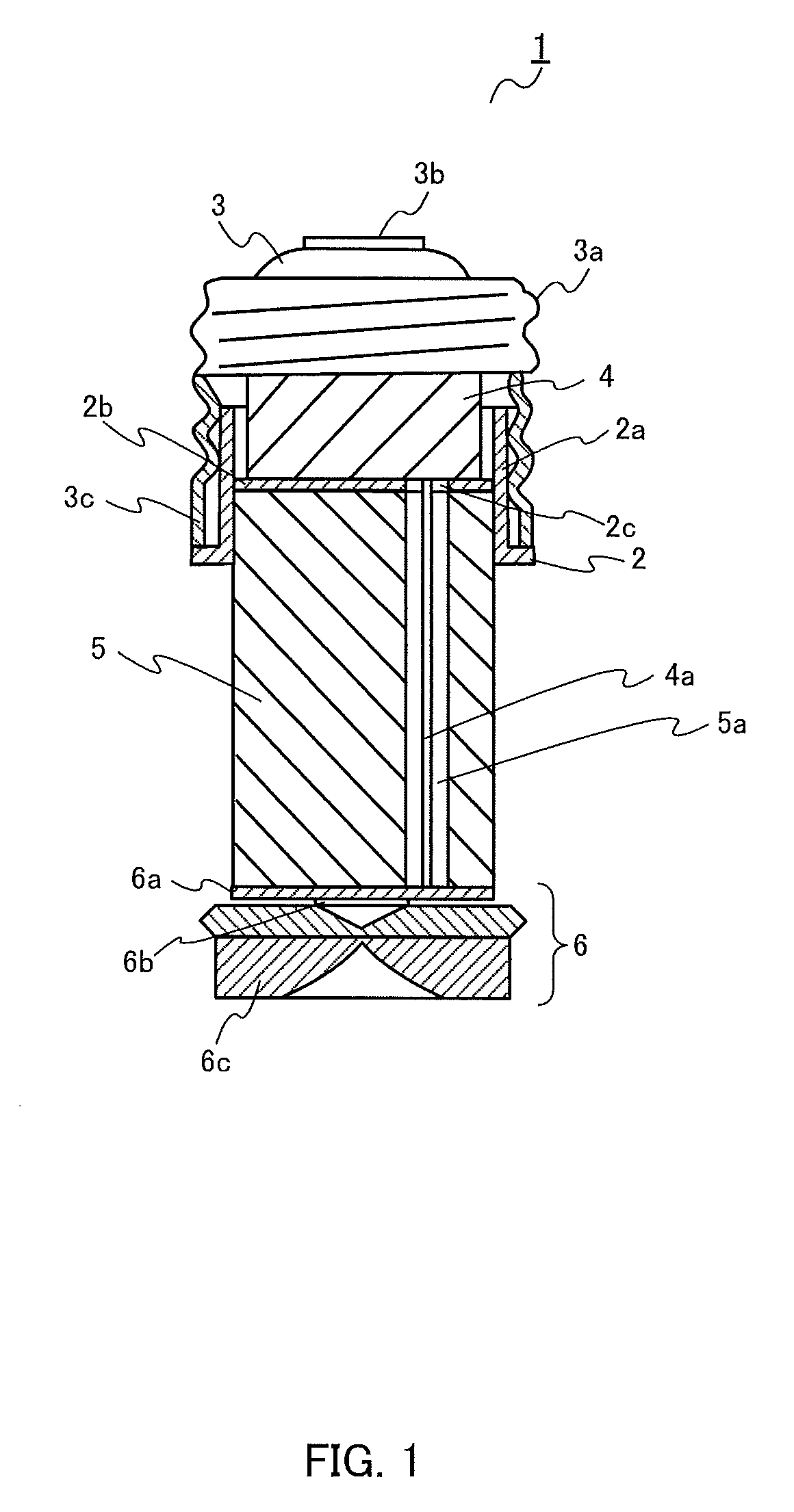
[0034]FIG. 1 illustrates LED bulb 1 having a light flux controlling member according to an embodiment of the present invention.

[0035]LED bulb 1 is mainly constituted by cover 2, base 3, power source unit 4, pedestal 5, and LED unit 6.

[0036]Cover 2 is made of a metal (for example, aluminum) that has high heat conductivity. Cover 2 is formed with cylindrical base attachment part 2a. Disk-shaped supporting member 2b that has hole 2c at a central part thereof is attached to an inner surface of base attachment part 2a with an adhesive or the like, and power source unit 4 is disposed on the inner surface of supporting member 2b.

[0037]Base 3 has metallic shell pa...


PUM


Abstract

An illumination device (1) has a light-emitting element (6b), and a luminous flux control member (6c) that includes a first lens (10) and a second lens (20). The first lens (10) and the second lens (20) are assembled such that a first surface (10c) and a second rear surface (20a) are in contact, or such that a minute gap exists between the first surface (10c) and the second rear surface (20a). A first conical concave surface (10d) having its apex on the central axis (C) is formed by indenting a first rear surface (10a). A second concave surface (20d), having its apex on the central axis (C) and having a curved shape the curvature of which decreases as the distance from the central axis increases, is formed by indenting a second surface (20c).

Description

TECHNICAL FIELD[0001]The present invention relates to a light flux controlling member for controlling a distribution of light emitted from a light-emitting element, and an illumination device having the light flux controlling member.BACKGROUND ART[0002]Traditional incandescent light bulbs generate a wide range of uniform light from a filament by supplying electric power from an external power source to the filament. However, the incandescent light bulbs have disadvantages such that power consumption is high, temperature is high, and lifespan is short.[0003]In contrast, since light-emitting diode (LED) bulbs have advantages such that lifespan is long, power can be saved, environmental pollution caused by waste does not occur, the LED bulbs are becoming lighting fixtures of a new age instead of the incandescent light bulbs. However, since the LEDs emit light only in a forward direction, when an LED bulb of the related art is attached to a ceiling, the light that is radiated to the cei...

Claims


Application Information

Patent Timeline
Patent Type & Authority Patents(United States)
IPC IPC(8): F21V5/00F21K99/00F21V3/00F21V5/04F21V7/00F21Y101/02
CPCF21V5/04F21K9/135F21K9/50F21V5/008F21Y2101/02F21V3/00F21V7/0091F21K9/232F21K9/60F21Y2115/10
Inventor NAKAMURA, MASATO
Owner ENPLAS CORP
Why Eureka
Try Eureka