Archery bow stand

a bow and archery technology, applied in the field of archery bow stands, can solve the problems of increasing the risk of misalignment of sight, bow could be accidently trampled, dirt or sand coming into contact with the string pulley components, etc., and achieves the effect of low mass, quick and easy reattachment to the base member, and small and evenly distributed mass

Inactive Publication Date: 2006-05-02
HORN EDWARD
View PDF8 Cites 19 Cited by
  • Summary
  • Abstract
  • Description
  • Claims
  • Application Information

AI Technical Summary

Benefits of technology

[0006]It is therefore an object of the invention to provide a bow stand attachment which may remain on the bow without affecting the performance of the bow while it is being used. It is a further object of the invention to provide a bow stand with legs which can be quickly and easily removed and reattached as needed. It is also an object of the invention to provide a bow stand which has a base member which can remain on the bow so that the bow may be transported in its usual carrying case. It is also an object of the invention to provide a bow stand which mounts to the riser of the bow and does not affect the operation of the bow limbs. It is a further object of the invention to provide a bow stand which will not mar the external surface of the bow or its limbs.

Problems solved by technology

Historically, archers have merely laid their bows on the floor or ground surface with the handle and limbs resting on the floor or ground which can scuff or mar the surfaces of the bow components and may result in dirt or sand coming in contact with the string pulley components.
Laying the bow on the ground or floor increases the risk of misaligning the sight and of course, the bow could be accidently trampled on.
If an upright wall or other structure is nearby, the archer may set the bow on the ground or floor surface and lean the upper end of the bow against the upright structure with the lower string pulley resting on the ground or floor, increasing the likelihood of damage and wear to the lower pulley, with the concomitant risk that the bow will not be stable and will fall over.
This device cannot be left on the bow when shooting because its mass interferes with the action of the limb and therefore the accuracy of the shot.
In addition, the clamping action tends to chafe the surface finish of the bow limb, thereby reducing the value of the bow.

Method used


Image

  • Archery bow stand
  • Archery bow stand
  • Archery bow stand

Examples


Embodiment Construction

[0016]Throughout this description, like elements are identified with the same reference numerals.

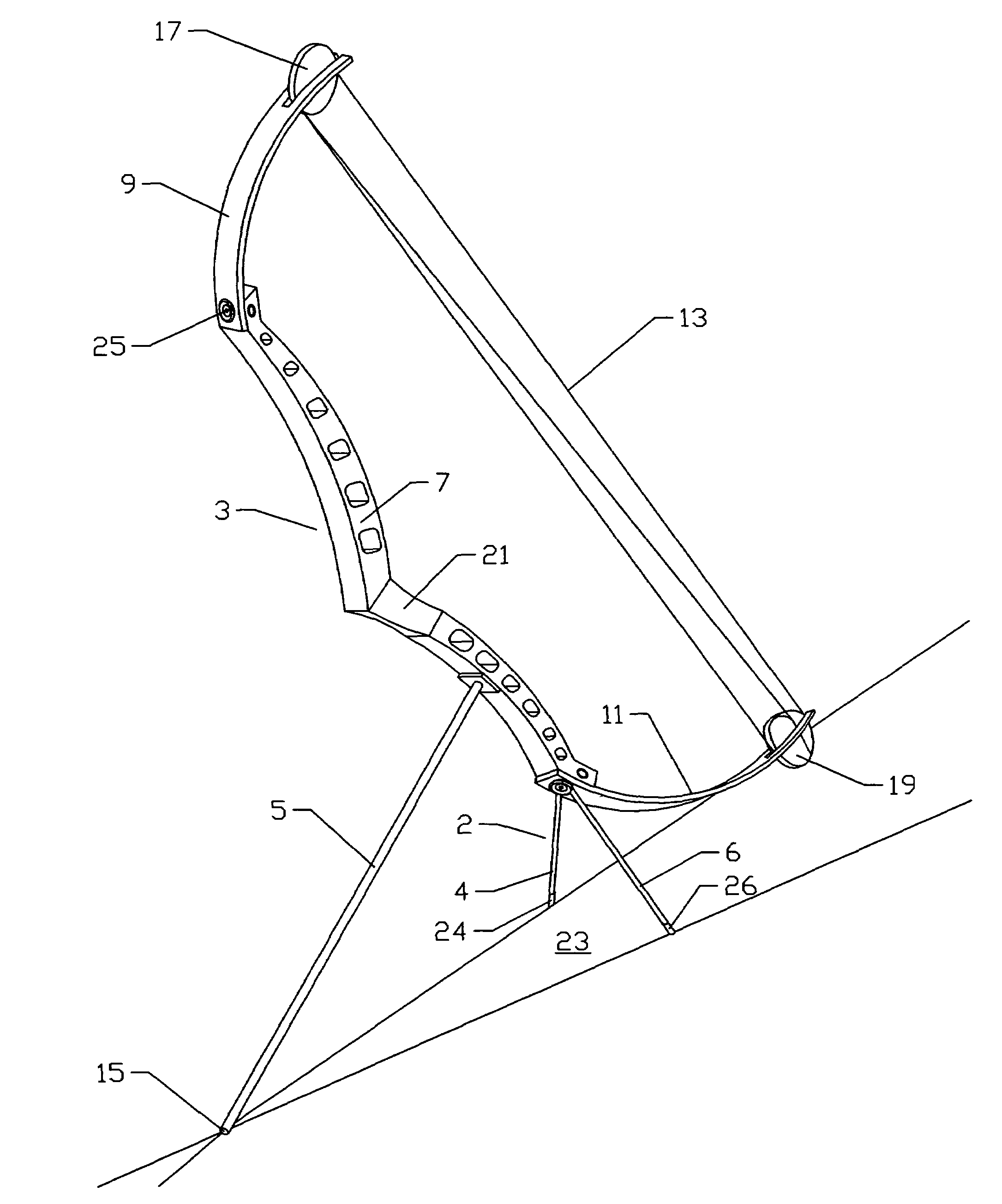
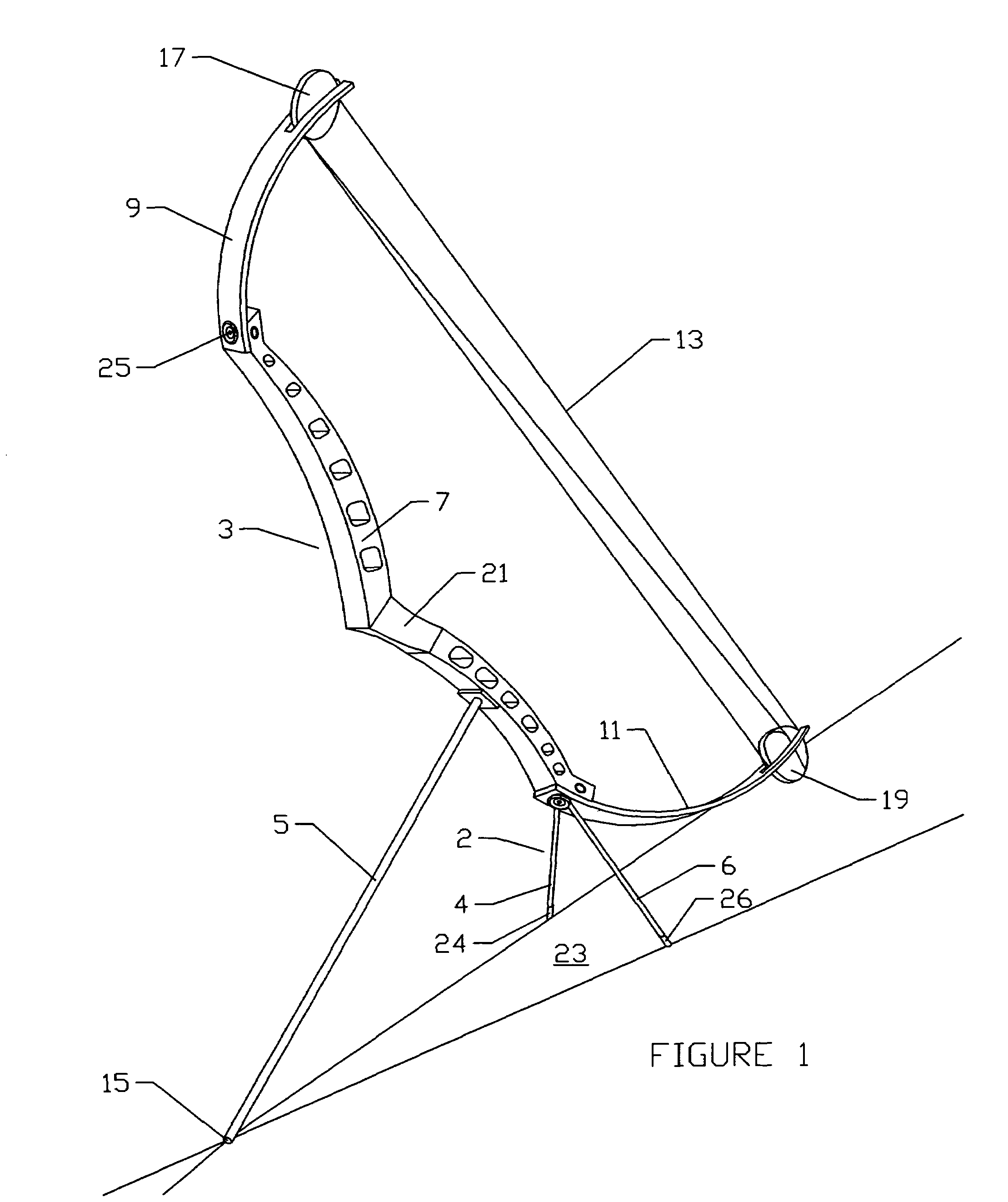
[0017]FIG. 1 illustrates a compound bow 3 resting on surface 23 supported on the free end 15 of a stabilizer 5 and on the invention 2 which has been mounted to bow 3. Bow 3 comprises a handle or riser 7 with an upper limb 9 and a lower limb 11 mounted thereto at its opposing ends. A conical washer 25 provides an adjustable connection for upper limb 9 to riser 7. Bow 3 includes a bowstring 13 which is strung between upper pulley 17 and lower pulley 19. Stabilizer 5 is a linear rod which is mounted to bow 3 below grip 21 and is a well known accessory for a target bow. Invention 2 comprises legs 4, 6 having free ends 24, 26 respectively which with free end 15 of stabilizer 5 define a plane. Legs 4, 6 cooperate with stabilizer 5 to form a tripod to support bow on floor surface 23 such that lower limb 11 and lower pulley 19 do not rest on floor surface 23. Critical to the effectiveness of inv...


PUM


Abstract

A bow stand attachment for an archery bow has a base which mounts to the riser of the bow. The base has a pair of legs extending downward from it. The legs are slid onto stubs which extend away and downward from the outer rim of the base. The ends of the legs and the end of a stabilizer mounted to the bow can cooperate to provide a supporting tripod for the bow. When no stabilizer is attached to the bow, the bow stand and lower pulley act as a tripod to support the bow. Performance of the bow is not affected by presence of the attachment because of its low mass and symmetry on the riser of the bow.

Description

STATEMENT REGARDING FEDERALLY SPONSORED RESEARCH OR DEVELOPMENT[0001]Not Applicable.BACKGROUND OF THE INVENTION[0002]In modern archery, compound bows are used which include a central handle section known as a riser, and limbs which extend from the upper and lower ends of the riser. The limbs are adjustable upon the ends of the risers by the tightening or loosening of fasteners mounting the limbs to the riser. The bowstring is strung between pulleys on the limbs. In hunting, target, archery, etc. the archer finds frequent occasions to set his or her bow down including while retrieving arrows from the target. Historically, archers have merely laid their bows on the floor or ground surface with the handle and limbs resting on the floor or ground which can scuff or mar the surfaces of the bow components and may result in dirt or sand coming in contact with the string pulley components. Laying the bow on the ground or floor increases the risk of misaligning the sight and of course, the b...

Claims


Application Information

Patent Timeline
Patent Type & Authority Patents(United States)
IPC IPC(8): F41B5/00F41B5/14
CPCF41B5/14
Inventor HORN, EDWARD
Owner HORN EDWARD
Why Eureka
Try Eureka