System and method for increasing upstream communication efficiency in an optical network

a technology of optical network and communication efficiency, applied in the field of video, voice, and data communication, can solve the problems of equipment cost and upwards of hundreds of thousands of dollars, and achieve the effects of reducing power down times of optical transmitters, increasing operating speeds, and increasing data transmission

Inactive Publication Date: 2006-05-02
ARRIS SOLUTIONS
View PDF71 Cites 9 Cited by
  • Summary
  • Abstract
  • Description
  • Claims
  • Application Information

AI Technical Summary

Benefits of technology

[0024]By adjusting the time constants mentioned above, the present invention can increase the operating speeds for both the optical transmitter housed in the subscriber optical interface and the optical receiver housed in the laser transceiver node. Specifically, when the time constants of the optical transmitter are adjusted, data transmission can be increased since the delays normally attributed to start-up and power down times for the optical transmitter can be significantly reduced. This start up and power down time reduction for an optical transmitter can substantially improve data transmission rates when optical transmitters share bandwidth according to data transmit timing schemes such as time division multiple access (TDMA).

Problems solved by technology

The aforementioned problems are linked to the hardware supporting the optical communications.
One of the problems associated with the SONET transmission standard that accentuates or magnifies the limitations of current conventional optical transmitters and receivers is that the minimum frequency content of data formatted according to the SONET standard can extend to very close to zero by virtue of the SONET standard permitting the transmission of up to 72 or more bits of the same type (the 1 or 0).
Another problem and drawback of conventional optical transmitters and optical receivers is that such equipment can have costs that approach (at the time of the writing of this text) of upward of hundreds of thousands of dollars.

Method used


Image

  • System and method for increasing upstream communication efficiency in an optical network
  • System and method for increasing upstream communication efficiency in an optical network
  • System and method for increasing upstream communication efficiency in an optical network

Examples


Embodiment Construction

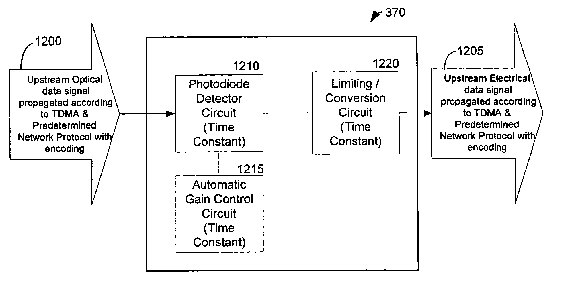
[0046]An optical transmitter of a subscriber optical interface and an optical receiver of a laser transceiver node can have time constants adjusted to a frequency of data that is formatted according to a predetermined network protocol, that is encoded with a predetermined coding scheme, and that is transmitted according to a predetermined data transmit timing scheme. A network protocol according to the present invention can comprise a network protocol that breaks up data into packets

[0047]The high frequency circuits present in the optical transmitter and optical receiver of the present invention can be adjusted for maximum efficiency when supporting data formatted according to a predetermined network protocol comprising Gigabit Ethernet, with a predetermined encoding scheme of 8B / 10B encoding, and data that is transmitted according to a predetermined data timing scheme comprising TDMA. Specifically, the time constants of two driver circuits of respective optical transmitters can be ...


PUM


Abstract

An optical transmitter of a subscriber optical interface and an optical receiver of a laser transceiver node can be designed to a frequency of data that is formatted according to a predetermined network protocol, that is encoded with a predetermined coding scheme, and that is transmitted according to a predetermined data transmit timing scheme. The frequency of data is an occupied frequency of a protocol when the data comprises a maximum number of like bits permitted by the protocol. An optical transmitter and optical receiver can be designed to a lowest occupied frequency of data that is encoded with 8B/10B encoding, and that is propagated upstream according to time division multiple access (TDMA). In this way, upstream optical communications can be maximized for speed.

Description

PRIORITY CLAIM TO PROVISIONAL AND NON-PROVISIONAL APPLICATIONS[0001]The present application is a division of Ser. No. 10 / 230,322 filed Jul. 5, 2001, now U.S. Pat. No. 6,654,565 which is a continuation-in-part of non-provisional patent application entitled “System and Method for Communicating Optical Signals between a Data Service Provider and Subscribers,” filed on Jul. 5, 2001 and assigned U.S. application Ser. No. 09 / 899,410, now U.S. Pat. No. 6,973,271. The present application also claims priority to provisional patent application entitled, “Method for Decreasing the Transition Time of TDMA Systems” filed on Aug. 28, 2001 and assigned U.S. application Ser. No. 60 / 315,555. The entire contents of both the non-provisional patent application and the provisional patent application mentioned above are hereby incorporated by reference.TECHNICAL FIELD[0002]The present invention relates to video, voice, and data communications. More particularly, the present invention relates to increasin...

Claims


Application Information

Patent Timeline
Patent Type & Authority Patents(United States)
IPC IPC(8): H04B10/00H04B10/272H04J14/02H04N7/173H04N7/22H04Q11/00
CPCH04J14/028H04J14/0282H04J14/0286H04N7/17309H04J14/0252H04Q11/0067H04J14/0232H04J14/0238H04J14/0247H04N7/22H04J14/0226H04Q11/0071
Inventor KENNY, JOHN J.
Owner ARRIS SOLUTIONS
Why Eureka
Try Eureka