Spear gun sight assembly

Inactive Publication Date: 2006-05-16
REED MARK A
View PDF20 Cites 6 Cited by
  • Summary
  • Abstract
  • Description
  • Claims
  • Application Information

AI Technical Summary

Benefits of technology

[0007]There has thus been outlined, rather broadly, the more important features of the invention in order that the detailed description thereof that follows may be better understood, and in order that the pr

Problems solved by technology

The above mounts, however, are not wel

Method used


Image

  • Spear gun sight assembly
  • Spear gun sight assembly
  • Spear gun sight assembly

Examples


Embodiment Construction

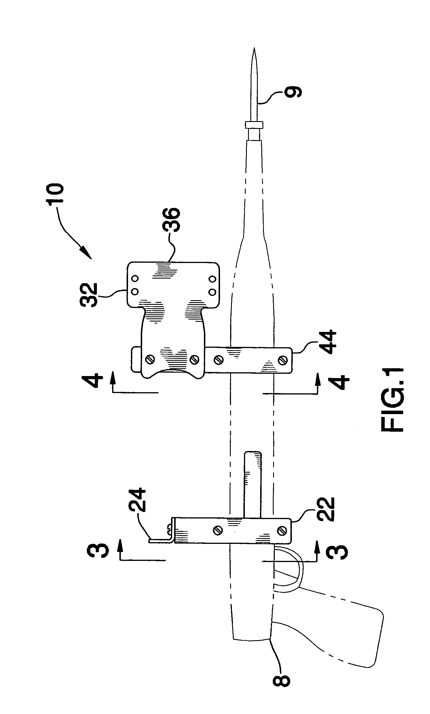
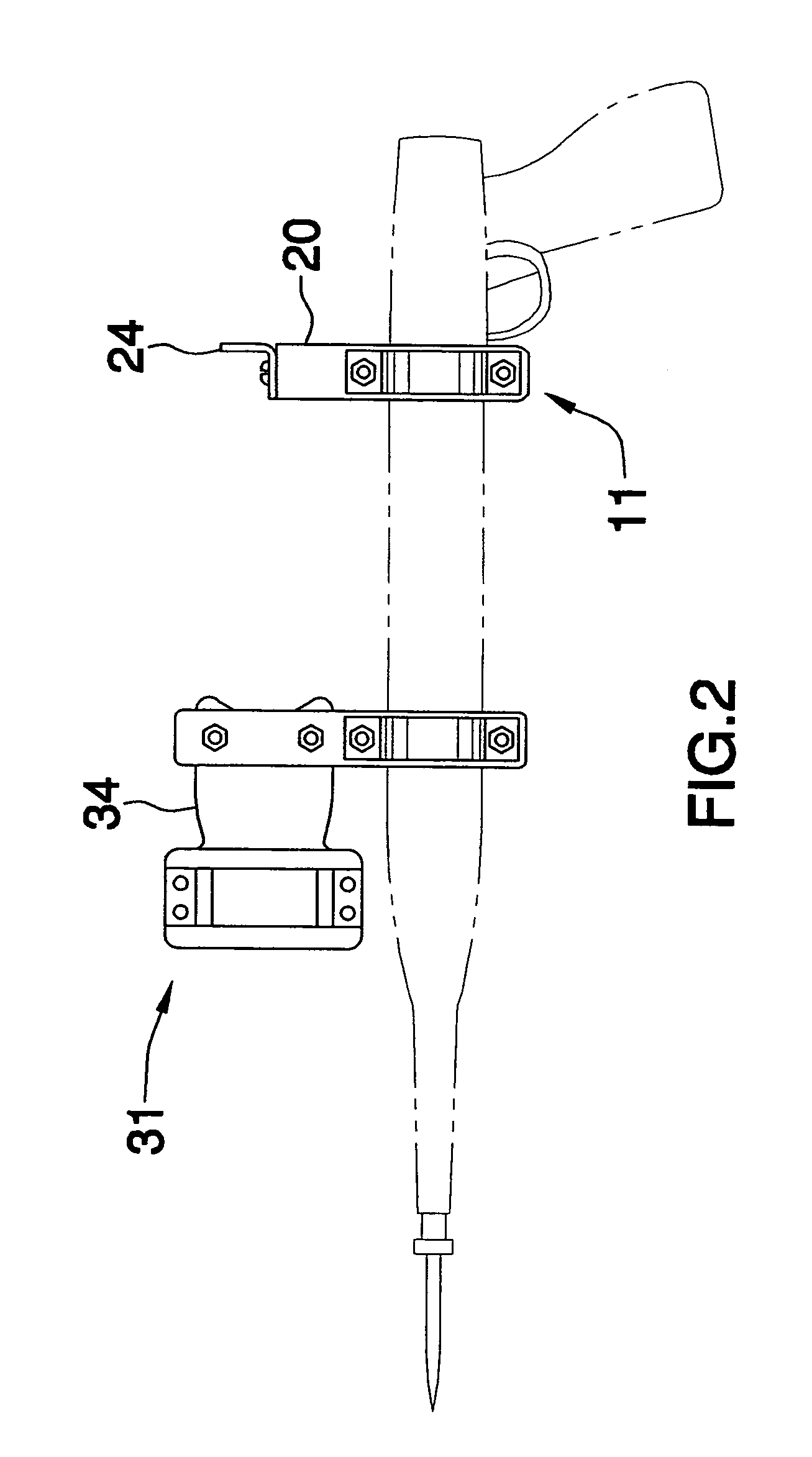
[0014]With reference now to the drawings, and in particular to FIGS. 1 through 4 thereof, a new gun sight assembly embodying the principles and concepts of the present invention and generally designated by the reference numeral 10 will be described.

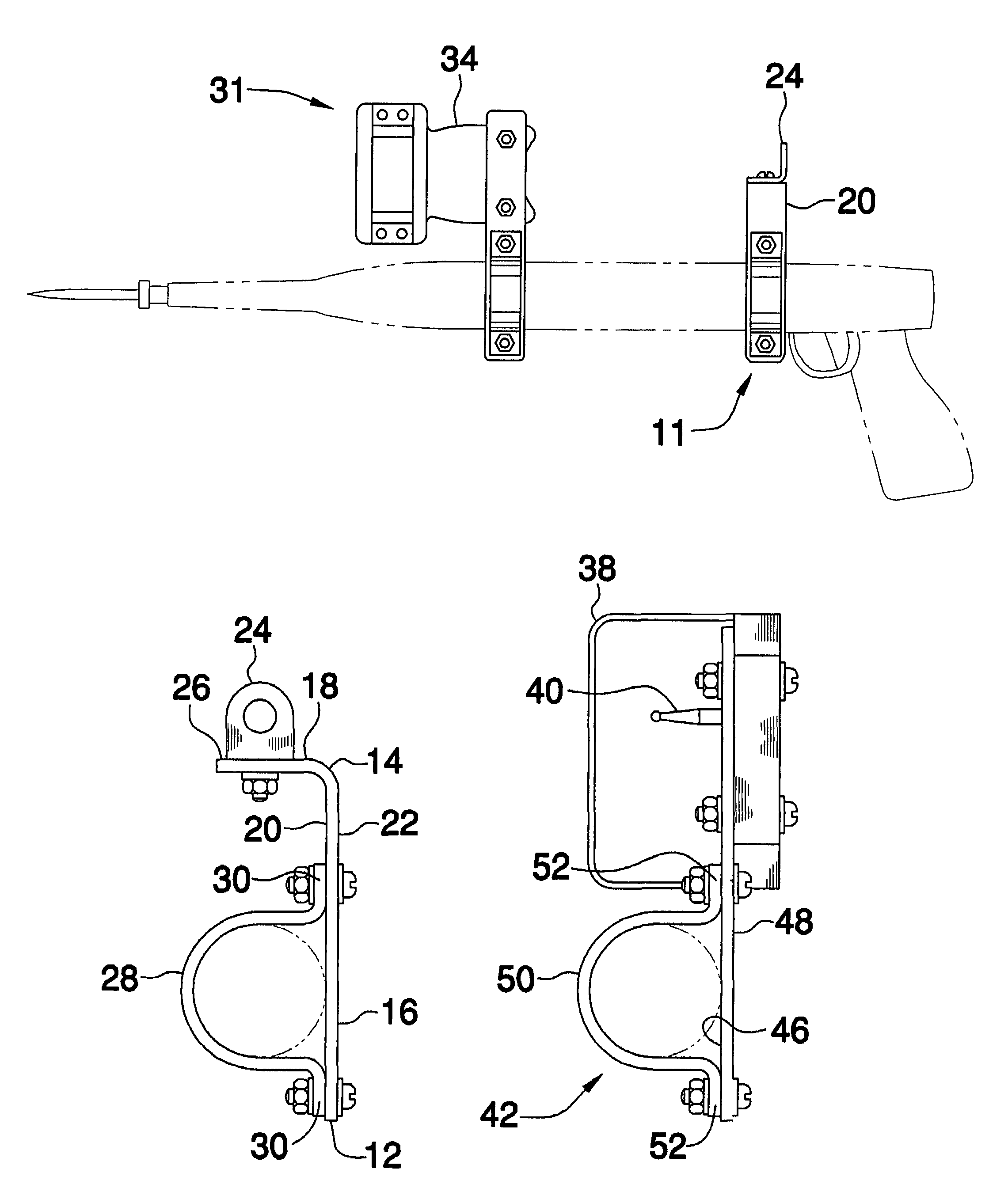
[0015]As best illustrated in FIGS. 1 through 4, the spear gun sight assembly 10 generally comprises a sight and bracket assembly to allow a person to attach a conventional bow sight to a spear gun 8. The assembly 10 includes a rear sight 11. The rear sight 11 comprises a first plate 12 that has a generally perpendicular bend 14 therein so that the first plate 12 includes a vertically orientated lower portion 16 and a horizontally orientated upper portion 18. The lower portion 16 has a first side 20 and a second side 22. A peep sight 24 is attached to and extends upwardly from a top side 26 of the upper portion 18. The peep sight 24 has a peephole extending therethrough. An axis of the peephole 24 is orientated parallel to a plane of the f...


PUM


Abstract

A spear gun sight assembly includes a rear sight with a first plate having a generally perpendicular bend therein such that a vertically orientated lower portion and a horizontally orientated upper portion are defined. A peep sight is attached to and extends upwardly from a top side of the upper portion. The peep sight has a peephole extending therethrough. A first coupler is adapted for releasably securing the rear sight to a spear gun. A front sight includes a second plate that has an inner side and an outer side. A loop is attached to the second plate so that the loop extends away from the inner side. A sight pin is attached to the second plate and extends into the loop. A second coupler is adapted for releasably securing the front sight to the spear gun so that the peephole is aligned with the sight pin.

Description

BACKGROUND OF THE INVENTION[0001]1. Field of the Invention[0002]The present invention relates to gun sight assemblies and more particularly pertains to a new gun sight assembly for removable attachment to a spear gun.[0003]2. Description of the Prior Art[0004]The use of gun sight assemblies is known in the prior art. U.S. Pat. No. 4,055,000 describes a device specifically designed for providing a sight for a spear gun. Another type of gun sight assembly is U.S. Pat. No. 4,044,486 which in particular describes a mounting assembly for mounting a scope onto a gun, such as a rifle. Another sight mount for mounting a scope onto a gun is shown in U.S. Pat. No. Des. 260,113. Yet another such mounting is shown in U.S. Pat. No. 4,418,487.[0005]While these devices fulfill their respective, particular objectives and requirements, the need remains for a device that allow for the mounting of a sight, and more particularly a bow sight, to a spear gun. A conventional bow sight includes a large loo...

Claims


Application Information

Patent Timeline
IPC IPC(8): F41G1/00F41G1/02F41G1/06
CPCF41G1/01F41G1/46F41G1/22F41G1/08
Inventor REED, MARK A.
Owner REED MARK A
Why Eureka
Try Eureka