Door Viewer Security Cover

a technology for viewing cameras and security covers, applied in special doors/windows, building components, doors/windows, etc., can solve problems such as compromising the security of persons located within the structur

Inactive Publication Date: 2013-05-16
KHOSHKISH KAMRAN
View PDF3 Cites 4 Cited by
  • Summary
  • Abstract
  • Description
  • Claims
  • Application Information

AI Technical Summary

Benefits of technology

[0004]The present invention is directed toward a security cover for a door viewer device such as a peephole. The security cover includes a housing including a forward aperture, a rearward aperture aligned with the forward aperture, and a shutter mechanism disposed between the apertures. The shutter mechanism is repositio

Problems solved by technology

First, conventional door viewer devices permit two-way viewing.
By noting changes in light within the peephole (e.g., from light to dark), the outside viewer is alerted to the fact that some

Method used


Image

  • Door Viewer Security Cover
  • Door Viewer Security Cover
  • Door Viewer Security Cover

Examples


Embodiment Construction

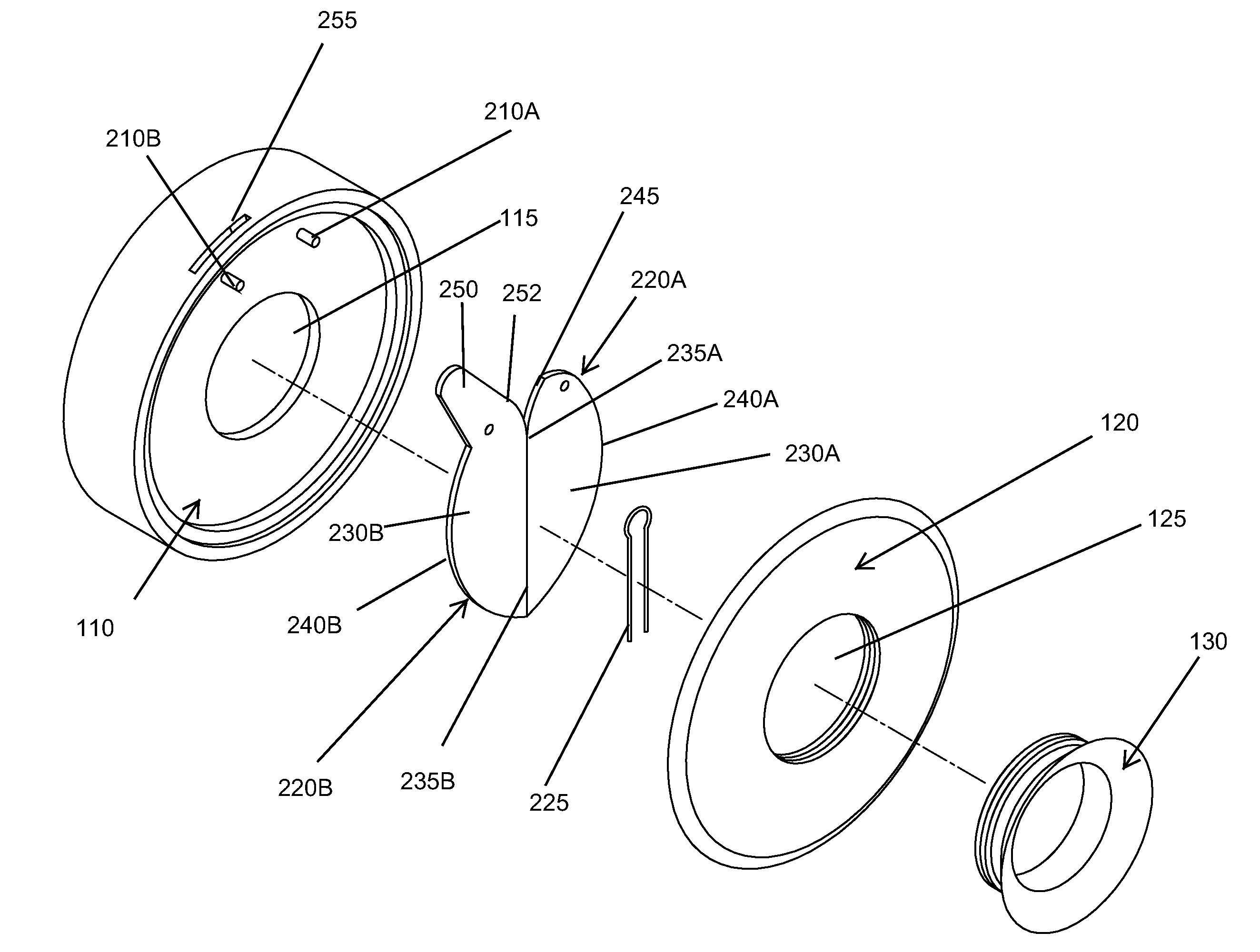
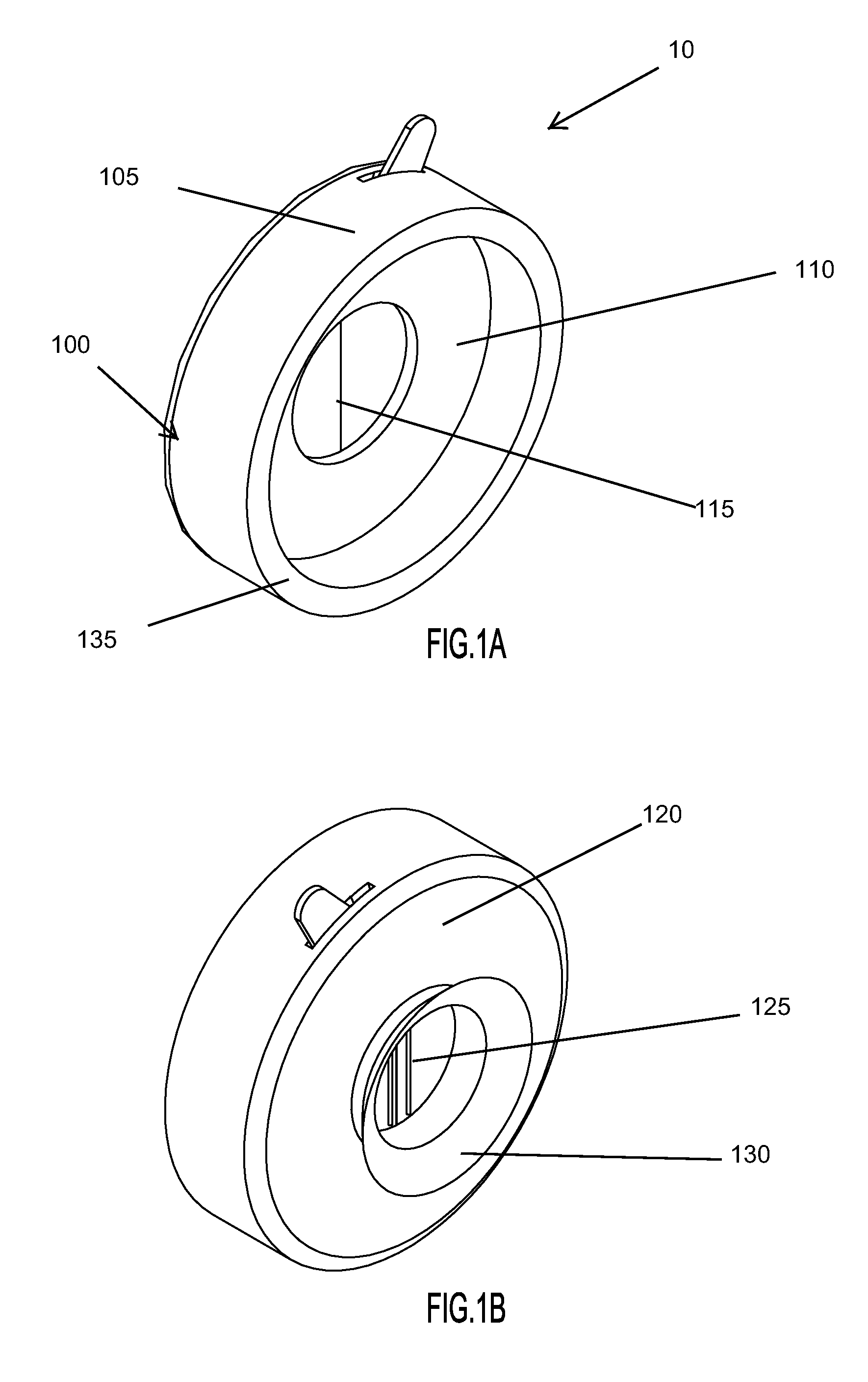
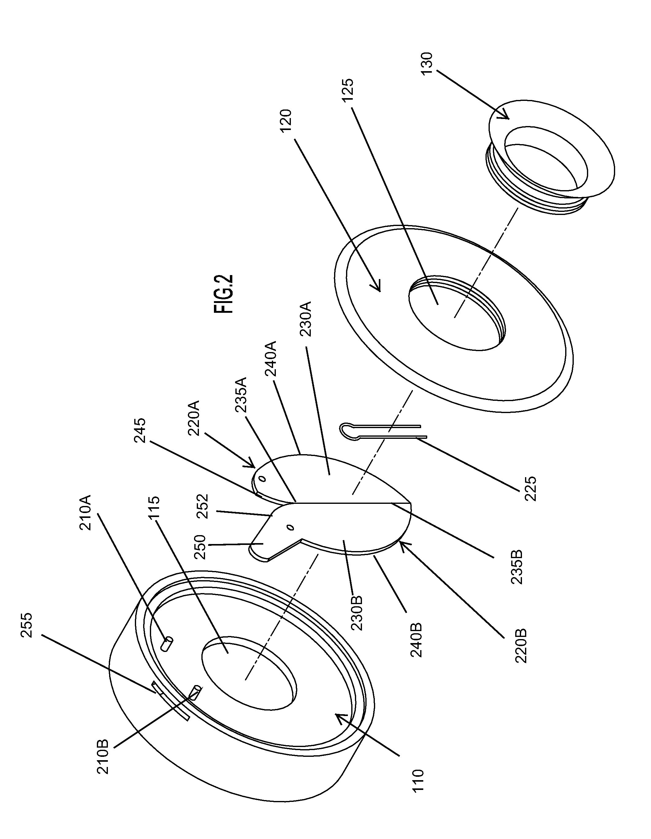
[0018]FIGS. 1A and 1B illustrate a security cover for a door view in accordance with an embodiment of the invention. As shown, the security cover 10 includes a housing 100 having a generally cylindrical side wall 105, an annular forward plate 110 defining a forward aperture 115 and an annular rearward plate 120 defining a rearward or viewing aperture 125. An eyecup or eye shield 130 (e.g., similar to those found on binoculars) is coupled to the rearward plate 120, surrounding the viewing aperture. As shown, the forward plate 110 is inset within the body 100, defining a forward, generally annular rim 135 operable to contact the door surface. The rim 135 may be treated such that it couples to the door surface. By way of example, the rim 135 may be coated with an adhesive. In other embodiments, the security cover 10 may include one or more fastening members (e.g., grommets) extending radially from the housing body 100 to permit fasteners such nails or screws to be utilized to secure th...


PUM


Abstract

The present invention is directed toward a security cover for a door viewer such as a peephole. The security cover includes a housing having a forward opening configured to align with the peephole, a rearward viewing port, and an eyecup. The security cover further includes a shutter mechanism that is manually repositionable from a closed position to an opened position via engagement of an actuator. In operation, the security cover is coupled to a door such that it covers the door viewer.

Description

FIELD OF THE INVENTION[0001]The present invention relates to a security cover for a door viewer device such as a peephole.BACKGROUND OF THE INVENTION[0002]Door viewer devices are security devices that permit a viewer located on one side of the door (e.g., the inside of the door) to observe callers located on the other side of the door (e.g., the outside of the door). Such door viewer devices typically include a lens system that generates a virtual image of the various objects located in front of the door. In operation, a user positioned behind the door peers through the door viewer device to view the immediate area surrounding the door, thereby enabling the person to confirm the identity of persons or objects before opening the door. Conventional door viewer devices suffer from several disadvantages. First, conventional door viewer devices permit two-way viewing. That is, while door viewer devices permit the viewer on the inside to view the area located in front of the door, they fu...

Claims


Application Information

Patent Timeline
IPC IPC(8): E06B7/30
CPCE06B7/30
Inventor KHOSHKISH, KAMRAN
Owner KHOSHKISH KAMRAN
Why Eureka
Try Eureka