Packet switching network, packet switching equipment and network management equipment

Inactive Publication Date: 2006-05-16
HITACHI LTD
View PDF39 Cites 293 Cited by
  • Summary
  • Abstract
  • Description
  • Claims
  • Application Information

AI Technical Summary

Benefits of technology

[0018]It is a first object of this invention to provide a packet switching network, packet switching device, and a network management equipment which eliminate the need to set up connections to reduce a delay and a delay variation involved in data transfer and to reduce the number of con

Problems solved by technology

In this communication mode, because the resources are not released even when there is no traffic, the resource usage efficiency is low.
However, because the communication bandwidth is not always guaranteed in this communication, resource contention occurs as the whole resource usage ratio becomes high.
In addition, because data which could not be sent because of insufficient resources must be resent, the resources become more insufficient and, as a result, congestion may result.
However, ATM still has the two problems described above.
That is, ATM still requires complex call admission control and, in addition, results in congestion when the resources become insufficient.
However, telephones, LANs, and WANs (Wide Area Network) are used in real time communications and, therefore, the shift of all the communication facilities to those of ATM is not so easy.
In such global commun

Method used


Image

  • Packet switching network, packet switching equipment and network management equipment
  • Packet switching network, packet switching equipment and network management equipment
  • Packet switching network, packet switching equipment and network management equipment

Examples


Embodiment Construction

[0055]The preferred embodiments of this invention are described with reference to the drawings.

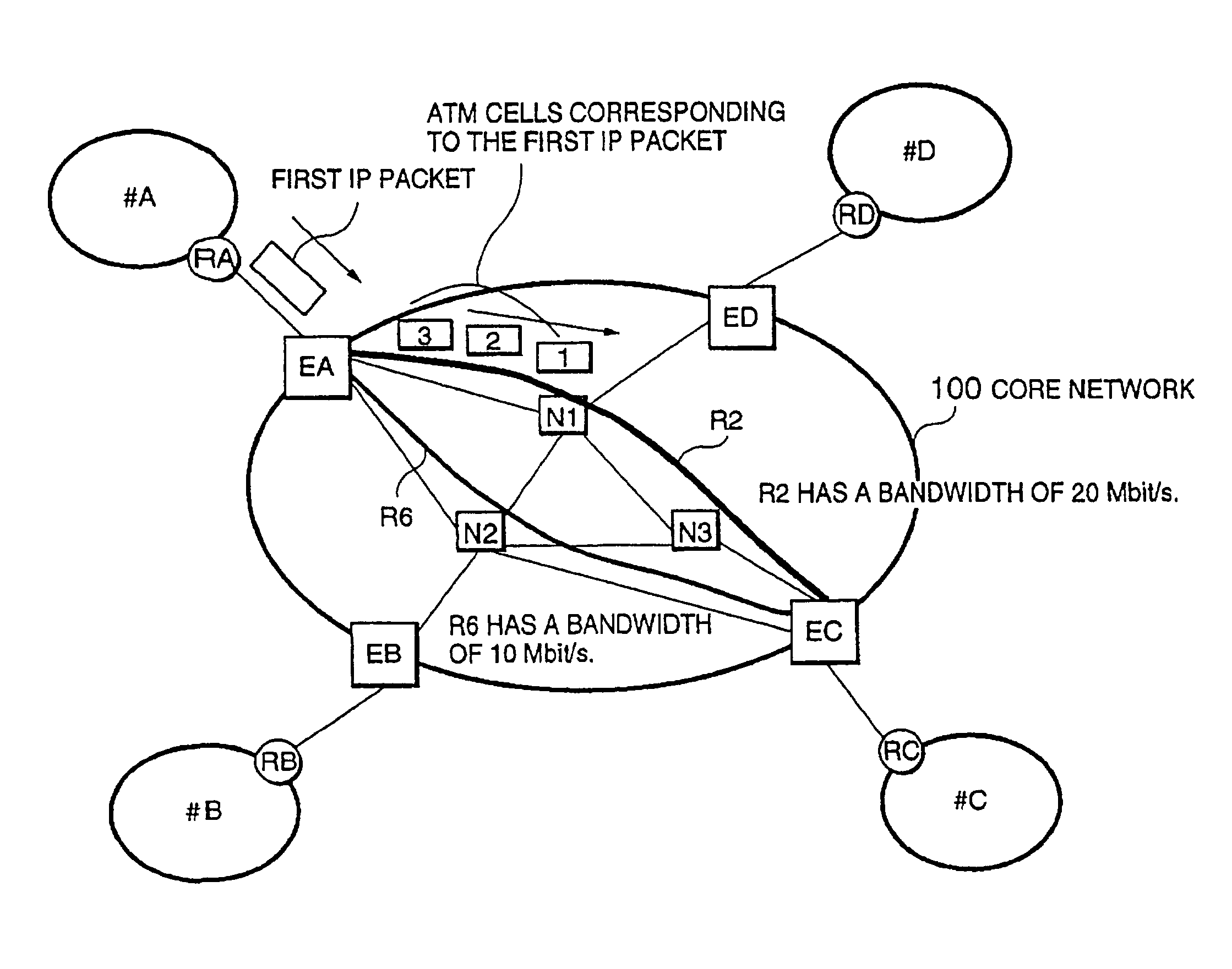
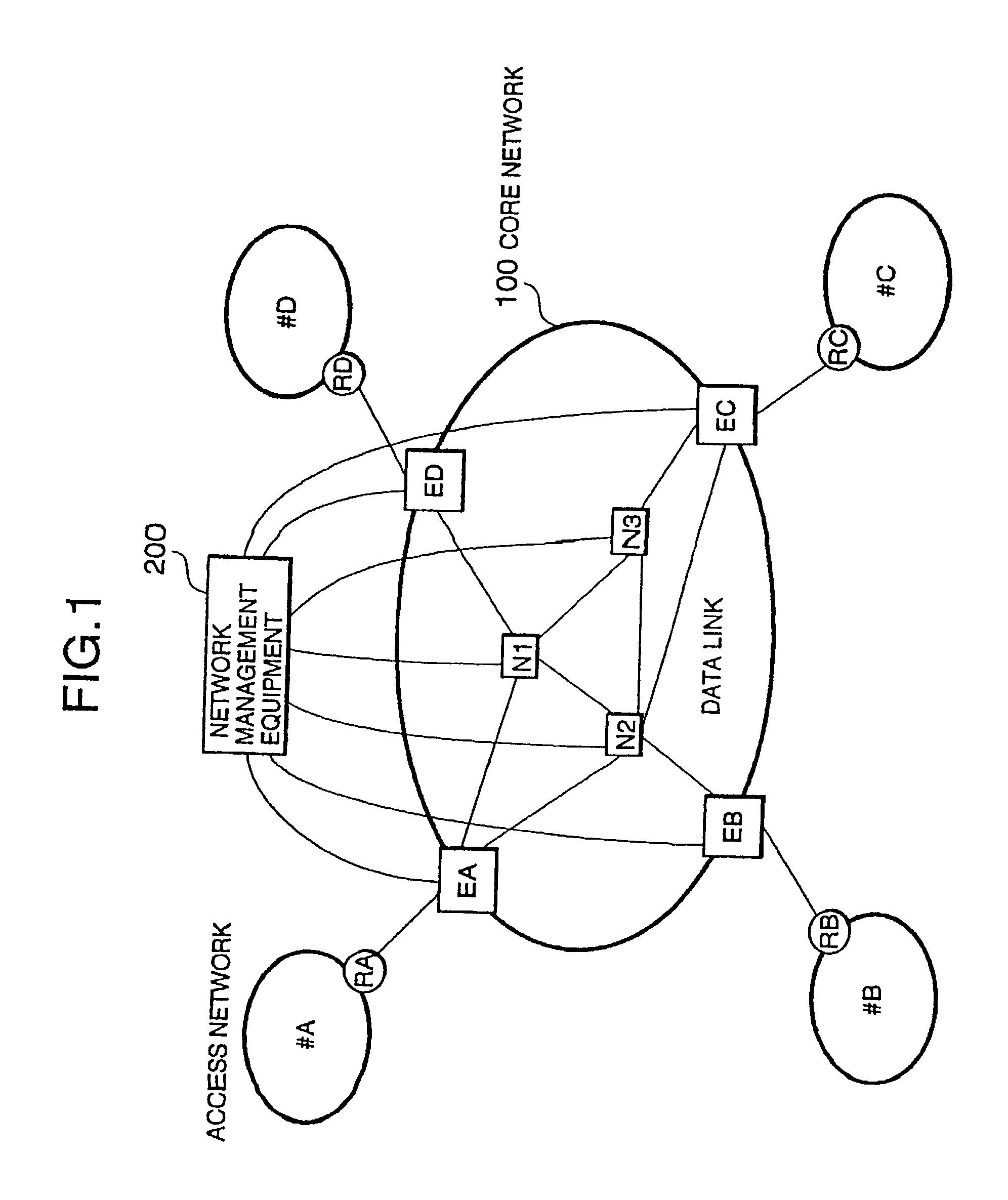
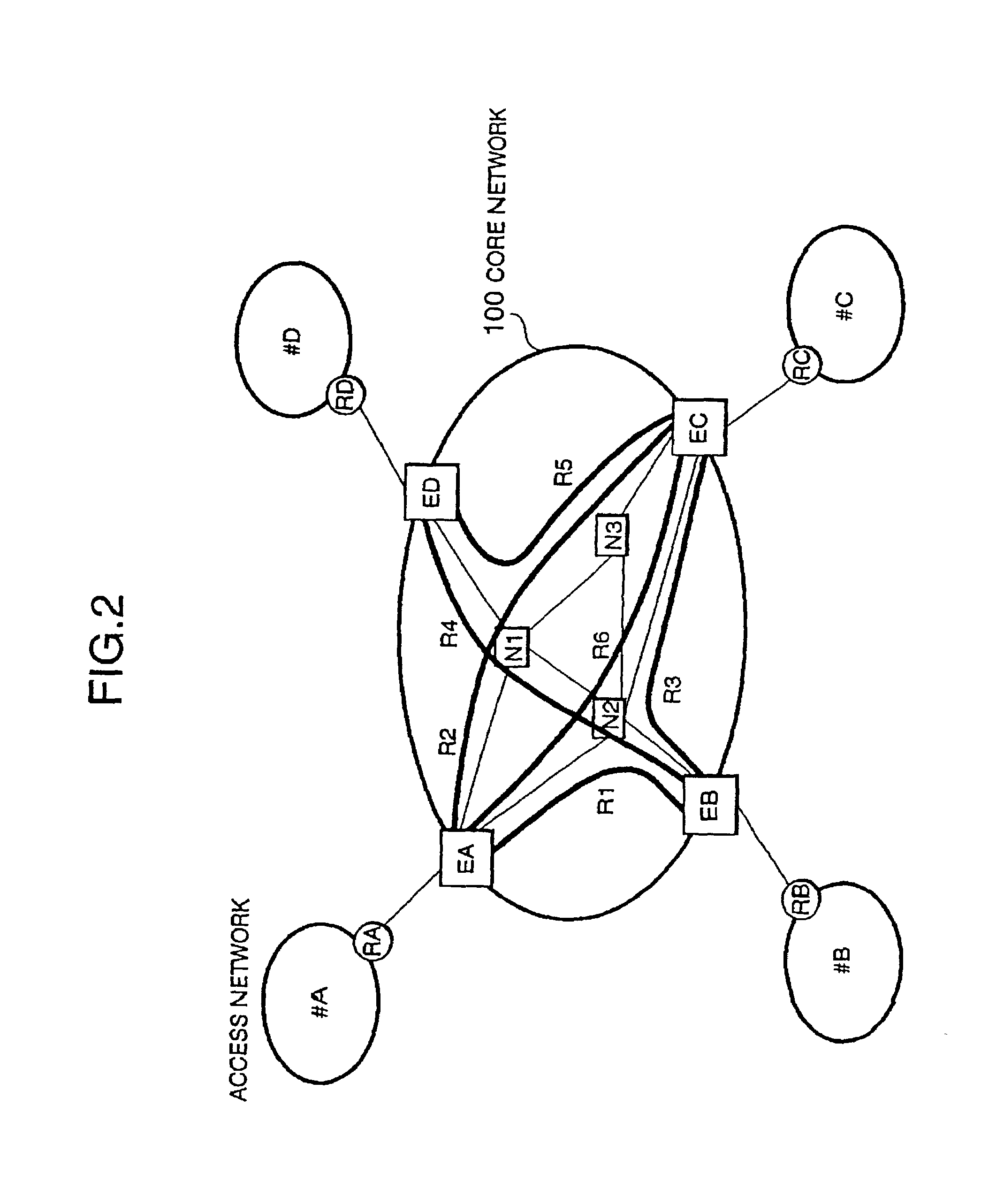
[0056]FIG. 1 is a diagram showing an embodiment of a packet switching network according to this invention. Sub-networks #A, #B, #C, and #D are connected to edge nodes EA, EB, EC, and ED via border routers RA, RB, RC, and RD. The network area surrounded by the edge nodes EA, EB, EC, and ED is called a core network. The sub-networks connected to the core network 100 are collectively called access networks. FIG. 1 shows the core network and the access networks with bold-line ellipses

[0057]The core network 100 is a connection-oriented network such as an ATM network. In FIG. 1, thin solid lines are drawn between edge nodes EA, EB, EC, and ED and relay nodes N1, N2, and N3. Edge nodes EA, EB, EC, and ED and relay nodes N1, N2, and N3 are connected to network management equipment 200 with control signal lines (shown in the figure with very thin lines).

[0058]A routing protocol within an access net...


PUM


Abstract

This invention provides a network management equipment and a packet switching equipment which eliminate a connection setup delay time, reduce a delay and a delay variation involved in data transfer, and effectively perform connectionless data flow processing in a large data network. The network is divided into a connection-oriented core network and a plurality of connectionless access networks connected to the core network where a plurality of connections (called permanent virtual route (PVR)) are set up among a plurality of edge nodes. The network management equipment selects one route from a plurality of PVRs for connectionless data flow received from one of the access networks and transfers data along the PVR.

Description

[0001]This application is a continuation of the U.S. continuation patent application Ser. No. 09 / 410,562 filed Oct. 9, 1999 now U.S. Pat. No. 6,512,745 which is a continuation application of U.S. patent application Ser. No. 09 / 093,265, filed on Jun. 8, 1998 now U.S. Pat. No. 6,108,304, which in turn claims a priority of a continuation-in-part application of U.S. patent application Ser. No. 08 / 810,733 filed on Mar. 4, 1997 now U.S. Pat. No. 6,002,668 and U.S. patent application Ser. No. 08 / 998,382 filed on Dec. 24, 1997 now U.S. Pat. No. 6,304,555.BACKGROUND OF THE INVENTION[0002]1. Field of the Invention[0003]This invention relates to a network, a packet switching network, a packet switching system, and network management equipment which efficiently process a large amount of connectionless data traffic using a connection-oriented network such as an ATM network.[0004]2. Description of Related Art[0005]Recently, as the Internet has rapidly evolved, networks and switching systems which...

Claims


Application Information

Patent Timeline
IPC IPC(8): H04L12/56H04L12/24H04L12/46H04L29/06H04Q11/04
CPCH04L12/24H04Q11/0478H04L12/5601H04L12/5602H04L12/5695H04L29/06H04L41/00H04L47/10H04L47/724H04L47/745H04L47/746H04L47/762H04L47/781H04L47/783H04L47/822H04L47/825H04L49/3081H04L12/4608H04L2012/5619H04L2012/5627H04L2012/563H04L2012/5632H04L2012/5635H04L2012/5642H04L2012/5645H04L2012/5647H04L2012/5649H04L2012/5658H04L2012/5667H04L2012/5679H04L47/70H04L9/40H04L41/344
Inventor ABE, HAJIMEMIKI, KAZUHOENDO, NOBORUTAKASE, AKIHIKOSAKURAI, YOSHITO
Owner HITACHI LTD
Why Eureka
Try Eureka