Low jitter tunable voltage control oscillator with self calibration circuits to reduce chip fabrication process variation

a voltage control and oscillator technology, applied in the field of voltage control oscillators, can solve problems such as substantial vco jitter, and achieve the effects of low jitter performance, high production yield, and significant improvement of system performan

Active Publication Date: 2016-03-10
RGT UNIV OF CALIFORNIA
View PDF0 Cites 0 Cited by
  • Summary
  • Abstract
  • Description
  • Claims
  • Application Information

AI Technical Summary

Benefits of technology

[0013]A tunable VCO providing low jitter can improve system performance significantly. In order to achieve low jitter performance in a VCO, the KVCO (frequency gain by control voltage) should be kept as small as possible over the target tuning frequency range. However, due to the existence of chip fabrication process variation, devices must be fabricated with substantially larger KVCO values to cover not only the target tuning frequency range but also the chip fabrication process variation. Typical process variation is about a 50% difference between slow-slow process corner and fast-fast process corner. If a VCO is designed for a 20% frequency tuning range, then due to process variation, KVCO must span a 70% tuning range instead of a 20% target tuning range. As a result, the unnecessarily high KVCO, which ensures a high production yield despite fabrication process variation, leads to substantial VCO jitter. Thus, in the present invention, KVCO can be kept smaller, as it does not need to be expanded beyond the target tuning frequency range to overcome tuning frequency changes caused by process variation.
[0014]The present invention is a tunable VCO which compensates for process variation by utilizing a novel architecture coupled with a self calibration circuit. This calibration of the VCO significantly reduces the effects of fabrication process variation and allows implementation of a VCO with low KVCO to cover the target tuning range. This implementation of VCO can significantly reduce jitter for a given target tuning range and span a wide range of chip fabrication processes.
[0015]The self calibration is realized by implementing feedback control circuits to create a constant RC delay for each stage of current mode inverter inside VCO. The method of combining the feedback control circuit and calibration circuit prevents the KVCO characteristic of the VCO from changing. The reduction of RC delay variation allows the value of KVCO to be minimized for a given device. Therefore, one can design a VCO with low KVCO to cover the target tuning frequency range despite the existence of process variation.
[0016]The self calibration circuit of the present invention provides a constant RC delay for current mode inverters inside a ring oscillator, as well as providing a constant voltage swing. This invention optimizes the performance of ring-type VCOs for any given fabrication process.
[0017]One unique element of the invention is that it creates a constant RC time for current mode logic inverters by utilizing automatic feedback circuits which emulate the external constant device to reduce the variation caused by the fabrication process variation. This invention not only optimizes the performance for a given process but also allows one to transport the design to different foundries. It will be appreciated that process variation within a given foundry is less than the process variation from one foundry to another foundry. In summary, this invention allows high performance and high manufacturing yield to be achieved using even simple ring-type VCOs.

Problems solved by technology

As a result, the unnecessarily high KVCO, which ensures a high production yield despite fabrication process variation, leads to substantial VCO jitter.

Method used


Image

  • Low jitter tunable voltage control oscillator with self calibration  circuits to reduce chip fabrication process variation
  • Low jitter tunable voltage control oscillator with self calibration  circuits to reduce chip fabrication process variation
  • Low jitter tunable voltage control oscillator with self calibration  circuits to reduce chip fabrication process variation

Examples


Embodiment Construction

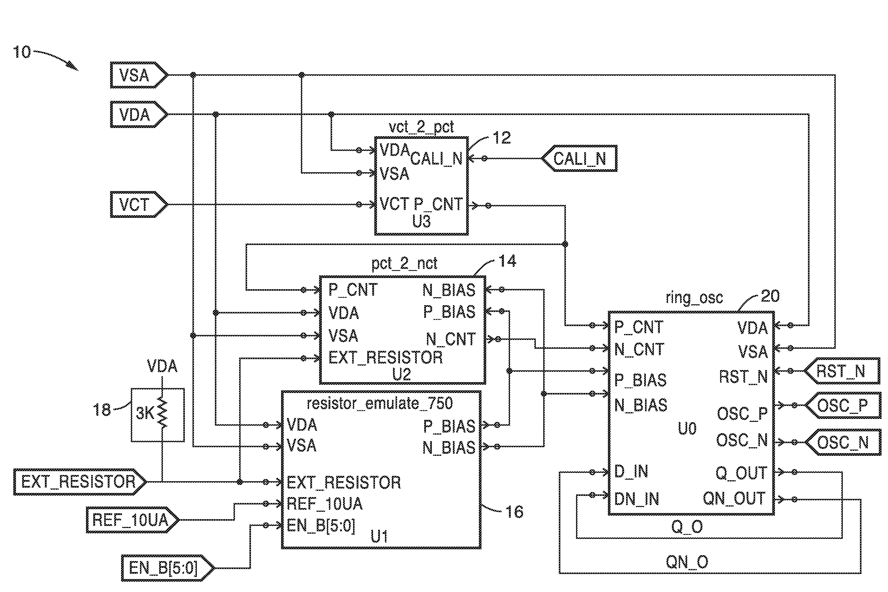
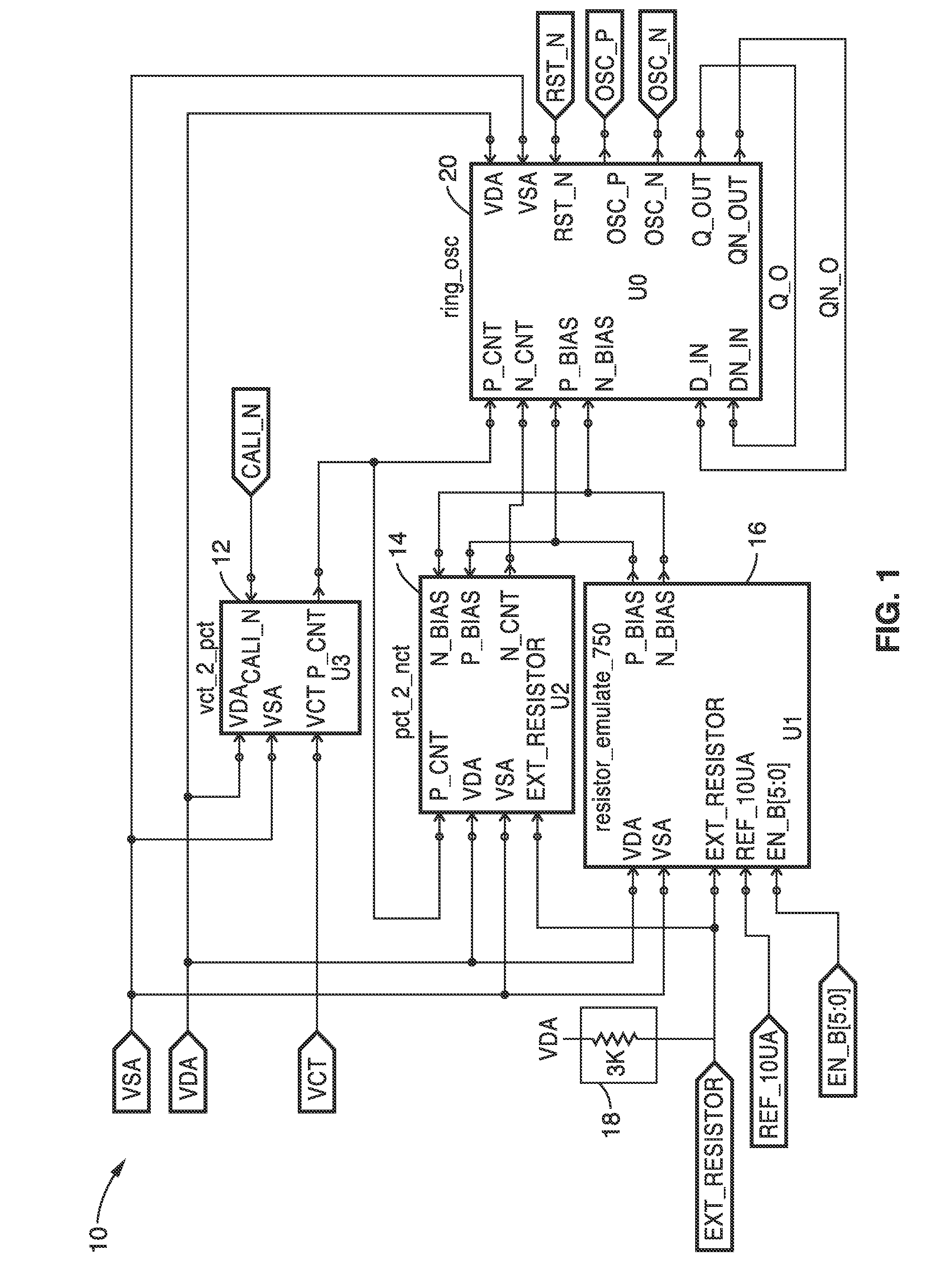
[0025]FIG. 1 illustrates an example embodiment 10 of the inventive voltage controlled oscillator (VCO) circuit. The VCO outputs a frequency (differential output OSC_P and OSC_N) in response to the voltage applied to its input (VCT). The oscillation frequency of a VCO circuit can be generally represented as:

fvco=f0+KvcoVCT  (1)

in which fvco is the frequency output by the VCO circuit in response to the center frequency f0 of the VCO offset by a VCO constant Kvco times the input control voltage VCT, herein represented simply as VCT. Thus, changing the input voltage VCT causes a proportional change in the output frequency of the VCO.

[0026]Example VCO circuit embodiment 10 is configured with four primary circuit elements: an amplifier 12, an adaptive bias current generator circuit 14 for keeping a constant voltage swing, a resistor emulator 16 operating in combination with resistor 18, and a ring oscillator circuit 20.

[0027]At the core of the VCO circuit is a variable oscillator. In the ...


PUM


Abstract

A voltage controlled oscillator (VCO) which can be configured with a smaller tuning range than is ordinarily required is presented. Ordinarily, the tuning range is selected much broader than the application warrants so that sufficient range is still provided despite VCO process variations. The inventive VCO is able to substantially eliminate the effects of process variation by utilizing a calibration circuit and process, so that variation in VCO device operation is minimized despite substantial process variation. Accordingly, the inventive VCO device is subject to reduced levels of jitter as its range need not be utilized for overcoming process variation arising during device fabrication.

Description

CROSS-REFERENCE TO RELATED APPLICATIONS[0001]This application is a 35 U.S.C. §111(a) continuation of PCT international application number PCT / US2014 / 018522 filed on Feb. 28, 2014, incorporated herein by reference in its entirety, which claims priority to, and the benefit of, U.S. provisional patent application Ser. No. 61 / 776,481 filed on Mar. 11, 2013, incorporated herein by reference in its entirety. Priority is claimed to each of the foregoing applications.[0002]The above-referenced PCT international application was published as PCT International Publication No. WO 2014 / 163881 on Oct. 9, 2014, which publication is incorporated herein by reference in its entirety.STATEMENT REGARDING FEDERALLY SPONSORED RESEARCH OR DEVELOPMENT[0003]Not ApplicableINCORPORATION-BY-REFERENCE OF COMPUTER PROGRAM APPENDIX[0004]Not ApplicableNOTICE OF MATERIAL SUBJECT TO COPYRIGHT PROTECTION[0005]A portion of the material in this patent document is subject to copyright protection under the copyright laws...

Claims


Application Information

Patent Timeline
Patent Type & Authority Applications(United States)
IPC IPC(8): H03K3/03
CPCH03K3/0315H03K3/011H03K3/0322
Inventor LEE, SHEAU JIUNGLI, YILEIVIRBILA, GABRIELCHANG, MAU-CHUNG FRANK
Owner RGT UNIV OF CALIFORNIA
Why Eureka
Try Eureka