Ventilation system for a cooking appliance

a technology for cooking appliances and ventilation systems, applied in the field of ventilation systems, can solve problems such as reducing the overall available surface area of cooktops

Inactive Publication Date: 2006-05-23
MAYTAG
View PDF18 Cites 30 Cited by
  • Summary
  • Abstract
  • Description
  • Claims
  • Application Information

AI Technical Summary

Problems solved by technology

However, the addition of a separate area dedicated to the controls reduces the overall available surface area of the cooktop.

Method used


Image

  • Ventilation system for a cooking appliance
  • Ventilation system for a cooking appliance
  • Ventilation system for a cooking appliance

Examples


Embodiment Construction

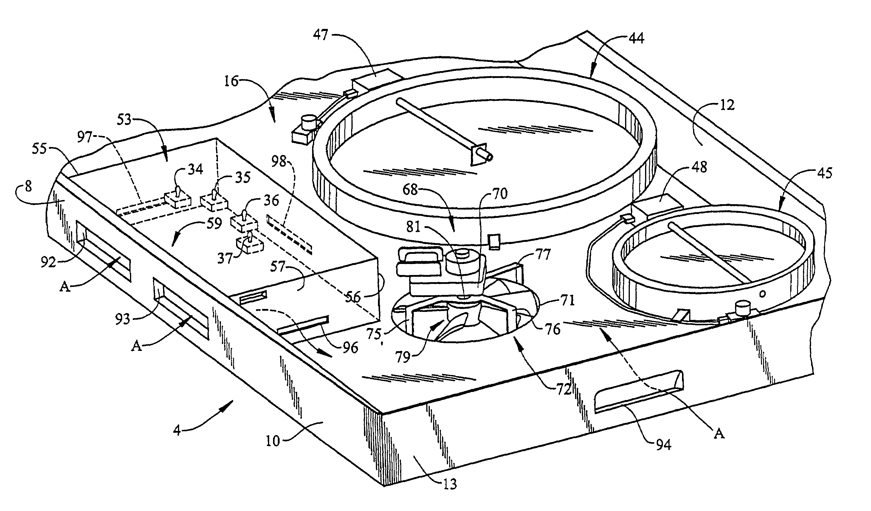
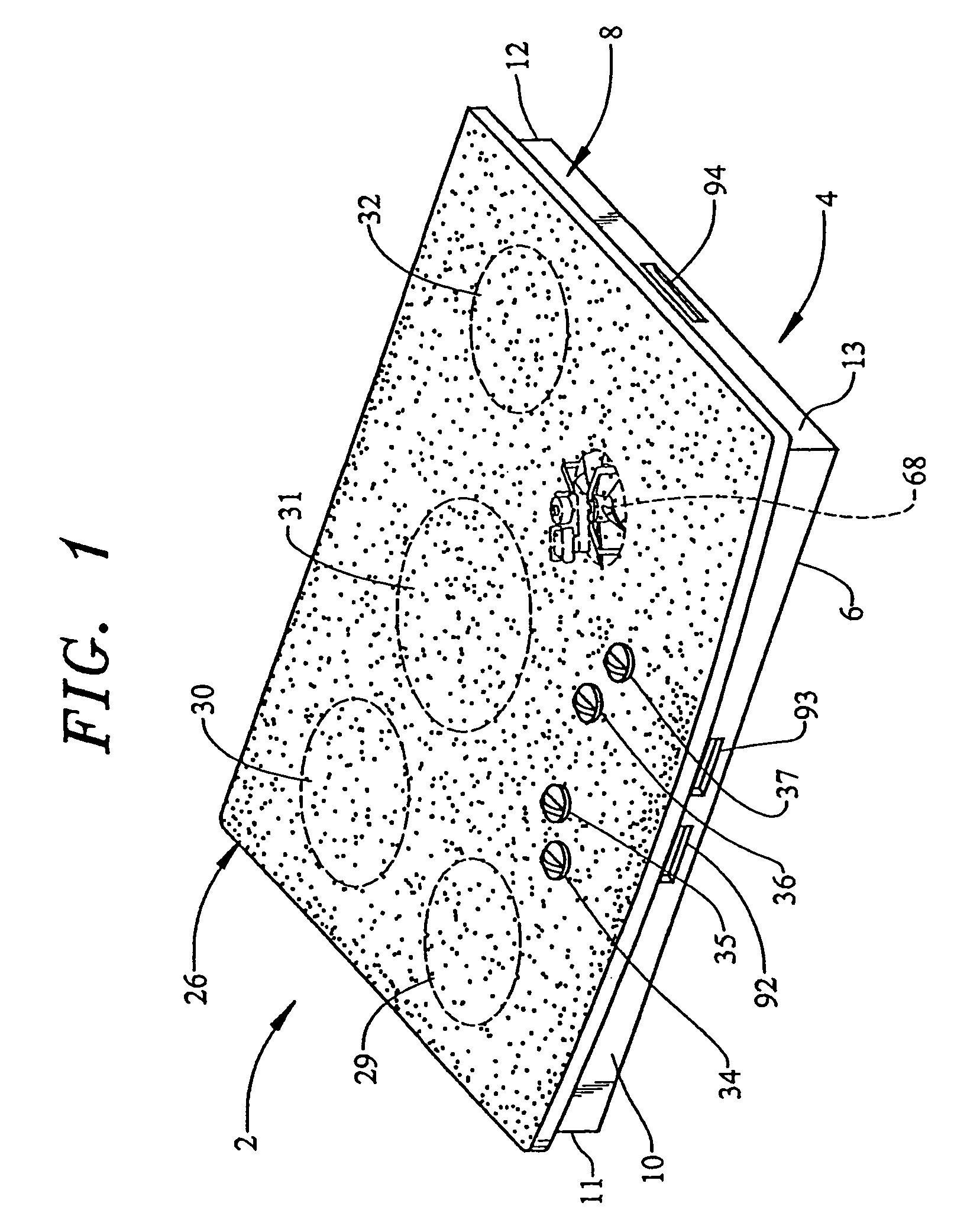
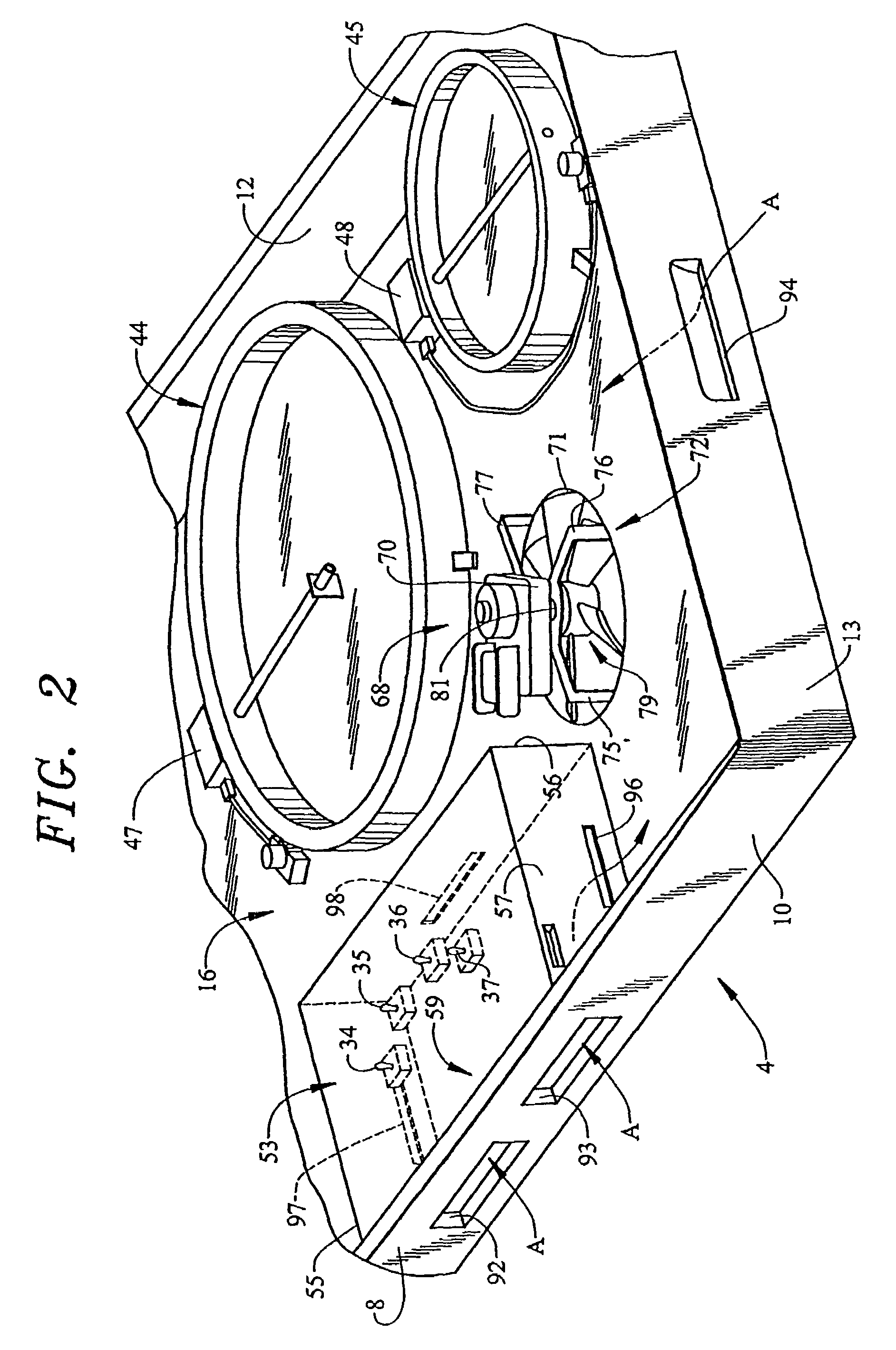
[0014]With initial reference to FIGS. 1 and 2, a cooking appliance constructed in accordance with the present invention is generally shown at 2. Although the actual cooking appliance into which the present invention can be incorporated may vary, the invention is shown in connection with cooking appliance 2 depicted as a cooktop model that is adapted to be arranged in a kitchen countertop. However, it should be understood that the present invention is not limited to this particular model type and could also be incorporated into various oven range configurations, e.g., both free-standing and slide-in ranges. In the embodiment shown, cooking appliance 2 includes a frame section 4 having a bottom wall 6 and a peripheral side portion 8. As shown, peripheral side portion 8 extends substantially perpendicularly upward from bottom wall 6 and is constituted by a plurality of side walls 10–13. In accordance with the invention, bottom wall 6 and peripheral side portion 8 combine to establish a...


PUM


Abstract

A cooking appliance includes a frame having a bottom wall for supporting heating elements and a peripheral side portion that extends from and about an outer periphery of the bottom wall so as to define a chassis upon which is arranged a cooktop. The peripheral side portion includes a plurality of openings that lead into the chassis. A control box is mounted in the chassis for housing control elements and associated electronics. The control box includes a plurality of side walls, with at least one of the side walls being provided with a vent which opens into the chassis. A fan is mounted within the chassis wherein, when the fan is activated, a cooling airflow is developed, with a first portion being drawn directly into the chassis, while a second portion first enters the control box housing before being directed into the chassis. A cover can be disposed beneath the chassis to guide and disperse the airflow.

Description

BACKGROUND OF THE INVENTION[0001]1. Field of the Invention[0002]The present invention pertains to the art of cooking appliances and, more particularly, to a ventilation system for developing an airflow that cools control elements, as well as an internal chassis portion, of a cooktop.[0003]2. Discussion of the Prior Art[0004]In general, smooth-top cooking surfaces are well known in the art and are generally associated with a range or mounted in a countertop. A typical cooktop includes a frame having secured thereto a plurality of heating elements which are covered by a glass-ceramic panel or other type of cooking surface. In addition, the cooktop includes a plurality of control elements, each of which is associated with operating a corresponding heating element mounted to the cooktop. In many cases, the cooktop includes openings that enable cooling air to pass through a top portion of the cooktop to draw away heat generated by the heating elements. The airflow can also be directed by...

Claims


Application Information

Patent Timeline
Patent Type & Authority Patents(United States)
IPC IPC(8): H05B3/68F24B5/04F24C15/10F24C15/32F24C15/34H05B3/74
CPCH05B3/74F24C15/101
Inventor ARNTZ, TIMOTHY J.BARRITT, WILLIAM D.ENSLEY, JEFFREYHAWKINS, DUSTIN L.
Owner MAYTAG
Why Eureka
Try Eureka