Hinge device

a technology of hinges and hinges, which is applied in the direction of instruments, wing accessories, and details of portable computers, etc., can solve the problems of difficulty in realizing both automatic closing lock functions

Inactive Publication Date: 2006-06-06
KATOH ELECTRIC MACHINERY
View PDF15 Cites 12 Cited by
  • Summary
  • Abstract
  • Description
  • Claims
  • Application Information

AI Technical Summary

Benefits of technology

[0007]An object of the present invention is to provide a hinge device for a portable intelligence terminal which can realize both an automatic closed lock function from a predetermined closed angle and a free-stop function at the time of opening and closing operation at the same time with a structure as simple as possible, when an opening and closing operation of a display device, which is comparatively massive second member, is conducted with regard to a keyboard main body, being the first member.

Problems solved by technology

Since a purpose of a hinge device shown in the laid-open patent official gazette is to control an opening-and-closing operation of the display device, being the second member, to the keyboard main body, being the first member, only with a cam mechanism, there arises a disadvantage that even for a compact type portable intelligence terminal having a comparatively massive display device, being the second member, it is difficult to realize both an automatic closed lock function from a predetermined closed angle, and a free-stop function at the time of opening and closing operation with regard to the keyboard main body, being the first member, of the display device.

Method used


Image

  • Hinge device
  • Hinge device
  • Hinge device

Examples


Embodiment Construction

)

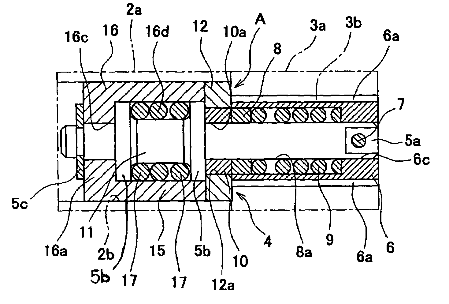
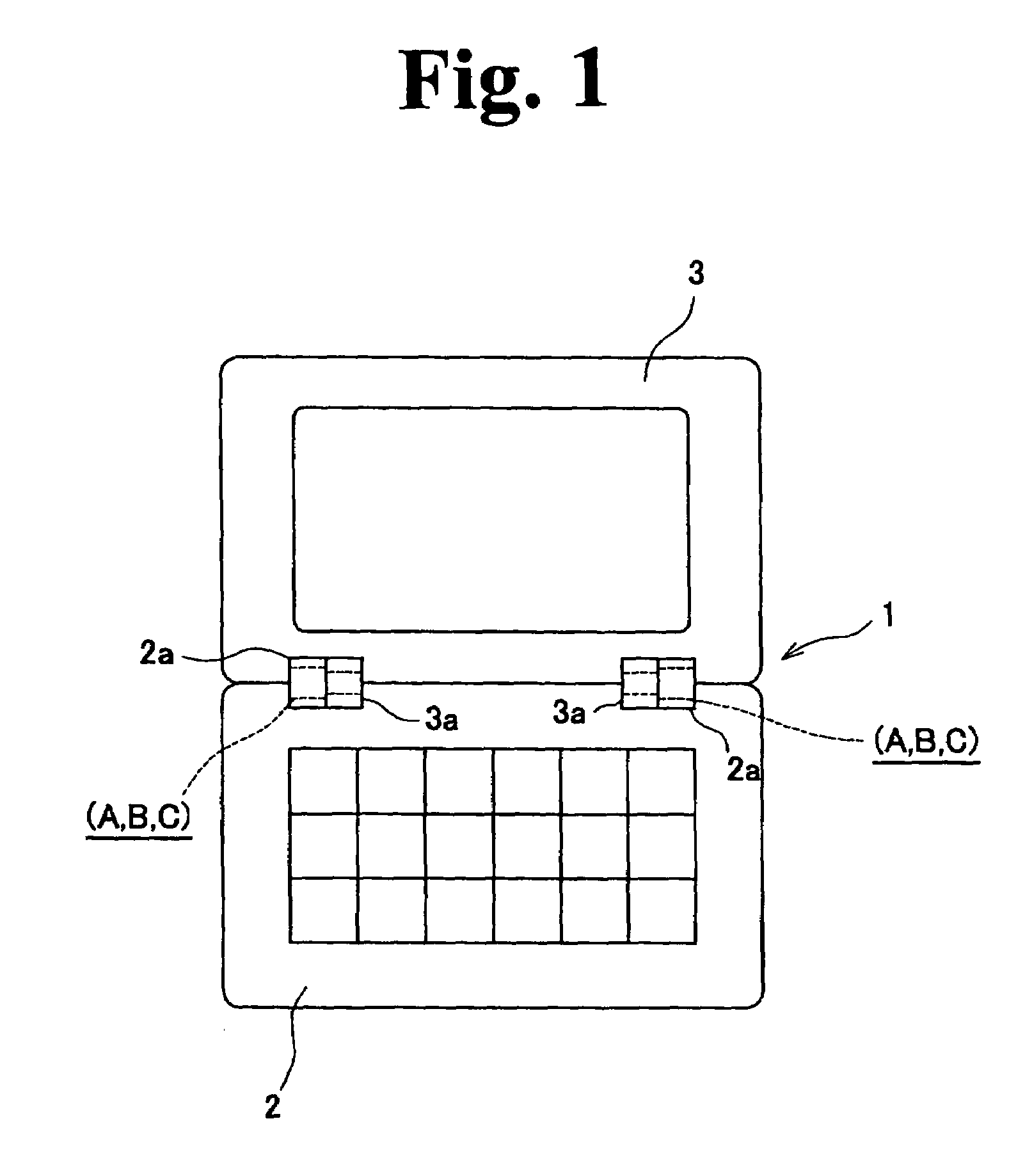
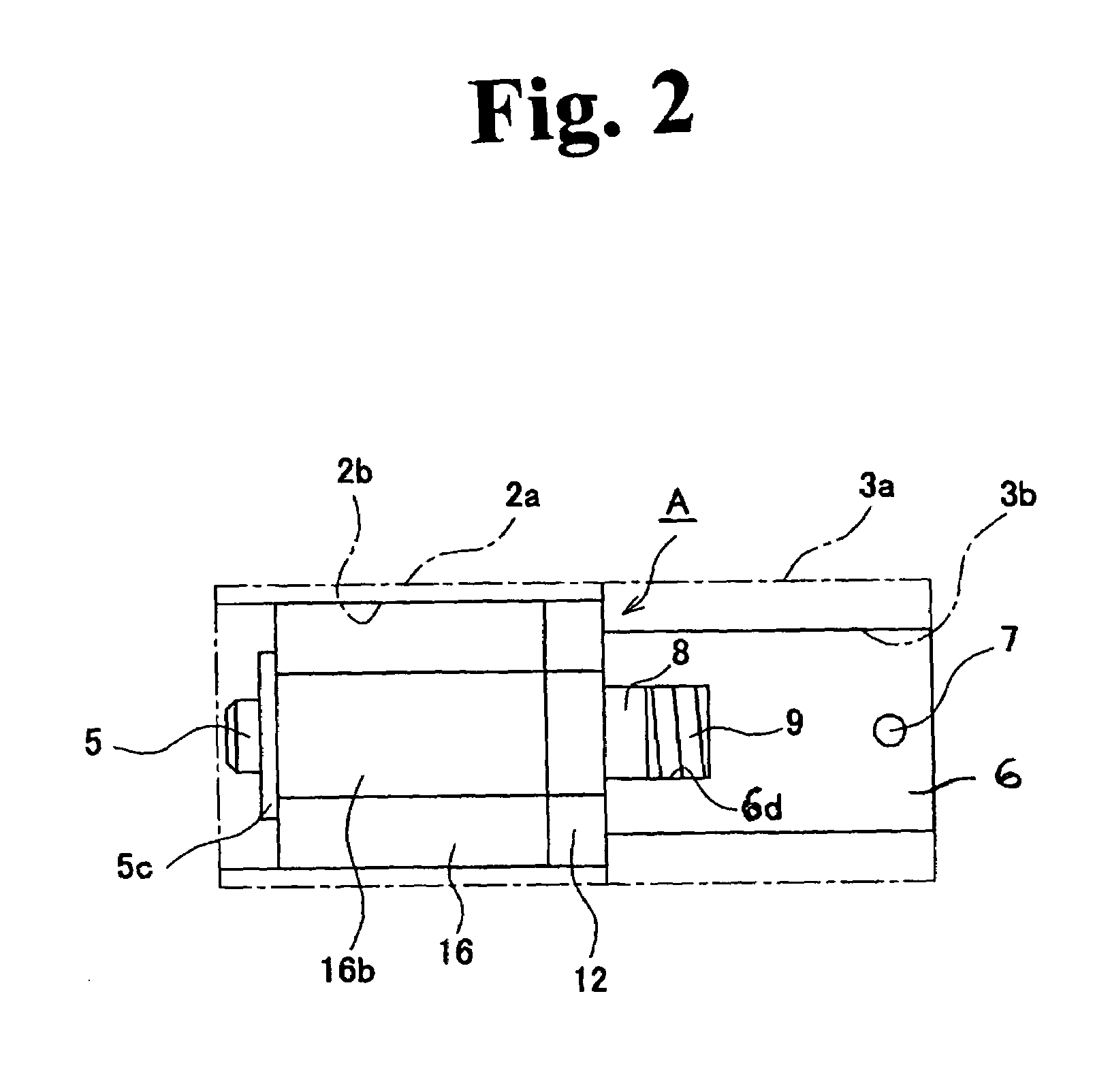
[0044]Drawings show an embodiment of the present invention. In FIG. 1, the one shown with a reference number 1 denotes, for instance, a portable intelligence terminal, and the one shown with a reference number 2 denotes a keyboard main body forming a first member. The one shown in a reference number 3 denotes a display device composed of, for instance, a liquid crystal display device which forms a second member.

[0045]The hinge devices A and A relating to the present invention are used for connecting the keyboard main body 2, being the first member, and the display device 3, being the second member, so that the key board main device and the display device can open and close relatively to each other, and installed between attachment portions 2a and 2a of the keyboard main body 2 and attachment portions 3a and 3a of the display device. Though the hinge devices A and A are provided in a pair in this drawing, they can be in one piece. Since the hinge devices A and A are bilaterally symm...


PUM


Abstract

A hinge device of a portable intelligence terminal, which connects a first member having a keyboard and a second member composed of a comparatively massive display device in an openable and closable manner as well as possible includes a cam mechanism and a friction mechanism coaxially on a shaft. The cam mechanism is structured with a fixing cam provided by allowing a shaft to insert through axially at each central portion into a cam case having a rotation arresting means fixed on the shaft, a slider cam provided slidably in a manner to confront to the fixing cam, being restrained its rotation by the cam case, and an elastic means to press the slider cam toward the fixing cam side, and the friction mechanism is structured with a friction ring attached to the shaft and fitted into the friction case with pressure having a rotation arresting means attached to the shaft in a manner to be rotatable, so that both of automatic closed lock function from a predetermined closed angle between the first and second members and a free stop function when opening and closing operation of the first and second members can be realized together without strain.

Description

BACKGROUND OF THE INVENTION[0001]1. Field of the Invention[0002]The present invention relates to a hinge device used for a portable intelligence terminal structured with a first member composed of a keyboard main body and a second member composed of a display device, in particular, suitable for use in connecting the second member, which is comparatively massive at a portion of the display device, to the first member in a openable and closable manner relatively.[0003]2. Description of the Relevant Art[0004]Conventionally, as this kind of a hinge device, a technology disclosed in a Japanese Patent Laid-open No. 2000-337008 is well-known.[0005]A hinge device disclosed in this laid-open patent official gazette includes: a shaft having an arresting portion at an end portion; a case body having a rotation arresting means allowing the shaft to be inserted through axially at the central portion and to be arrested at an arresting portion; a slider cam slidably arrested in a key groove provid...

Claims


Application Information

Patent Timeline
Patent Type & Authority Patents(United States)
IPC IPC(8): E05D11/08F16C11/10E05D11/10F16C11/04G06F1/00G06F1/16
CPCG06F1/1616G06F1/1681G06F1/1679E05D11/082E05D11/1078E05Y2900/606Y10T16/540255Y10T16/5403Y10T16/54035Y10T16/5387G06F1/00
Inventor NISHIHARA, TAICHI
Owner KATOH ELECTRIC MACHINERY
Why Eureka
Try Eureka