Surgical stapling instrument incorporating a tapered firing bar for increased flexibility around the articulation joint

a technology of stapling and firing bar, which is applied in the direction of surgical staples, surgical staples, surgical forceps, etc., can solve the problems of complicated approaches to articulating a stapling and severing

Inactive Publication Date: 2006-06-06
CILAG GMBH INT
View PDF29 Cites 2516 Cited by
  • Summary
  • Abstract
  • Description
  • Claims
  • Application Information

AI Technical Summary

Benefits of technology

[0017]On one aspect of the invention, a surgical instrument has a handle portion that produces an articulation motion and a firing motion that are transferred through a shaft having a longitudinal axis. An articulation mechanism coupling the shaft to an end effector and responsive to the articulation motion to rotate the end effector from the longitudinal axis of the shaft. A firing mechanism responds to the firing motion and is coupled for movement through the articulation mechanism and end effector. In particular, the firing mechanism has an actuating portion having a first thickness and positioned in the end effector and an articulation portion proximally attached to the actuating portion and having a second thickness less than the first thickness for articulating movement through the articulation mechanism. Thereby the firing mechanism is effective at both actuating the end effector and articulating through the articulation mechanism.

Problems solved by technology

Approaches to articulating a stapling and severing tend to be complicated by integrating control of the articulation along with the control of closing the end effector to clamp tissue and firing (i.e., stapling and severing) the end effector within the small diameter constraints of an endoscopic instrument.

Method used


Image

  • Surgical stapling instrument incorporating a tapered firing bar for increased flexibility around the articulation joint
  • Surgical stapling instrument incorporating a tapered firing bar for increased flexibility around the articulation joint
  • Surgical stapling instrument incorporating a tapered firing bar for increased flexibility around the articulation joint

Examples


Embodiment Construction

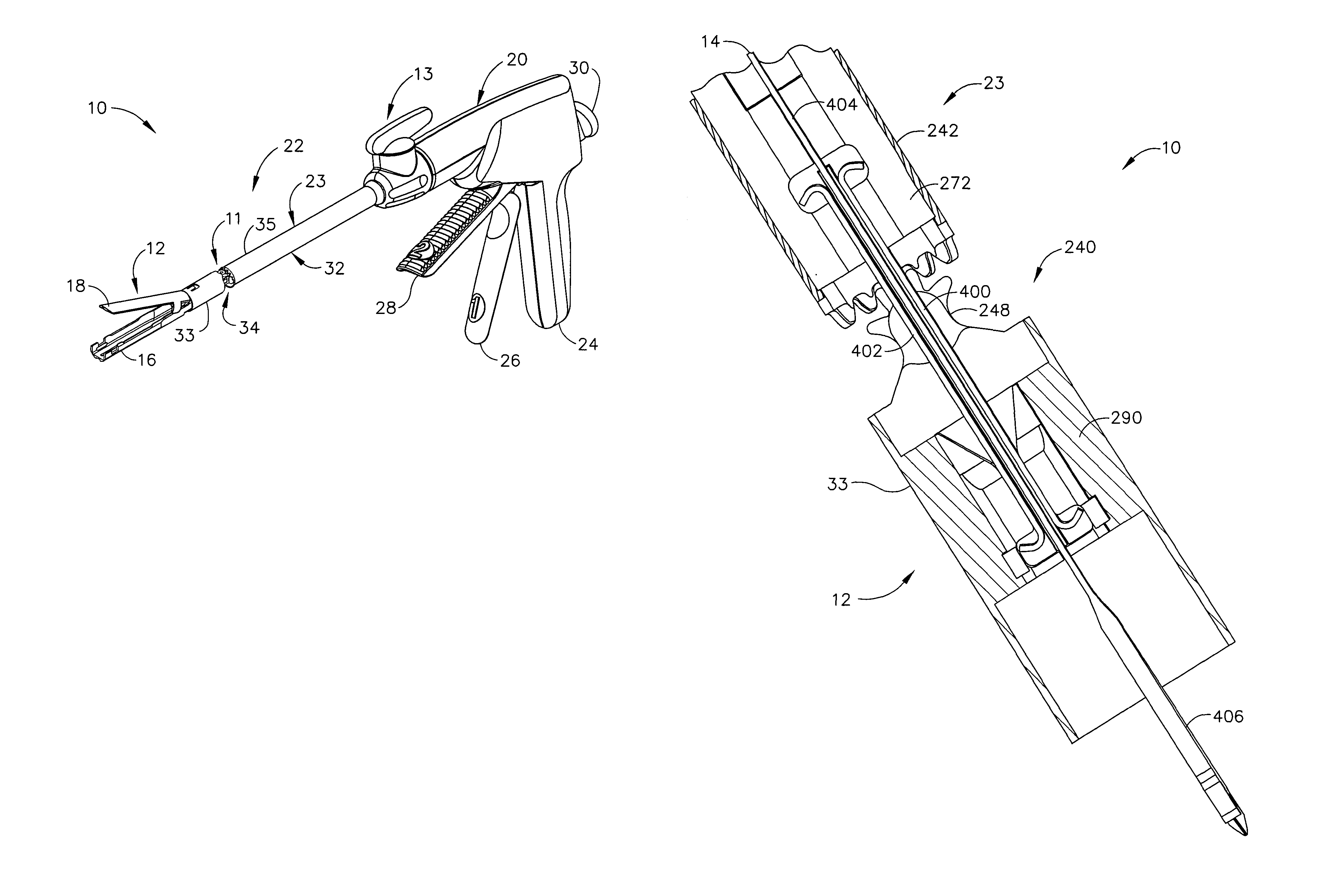
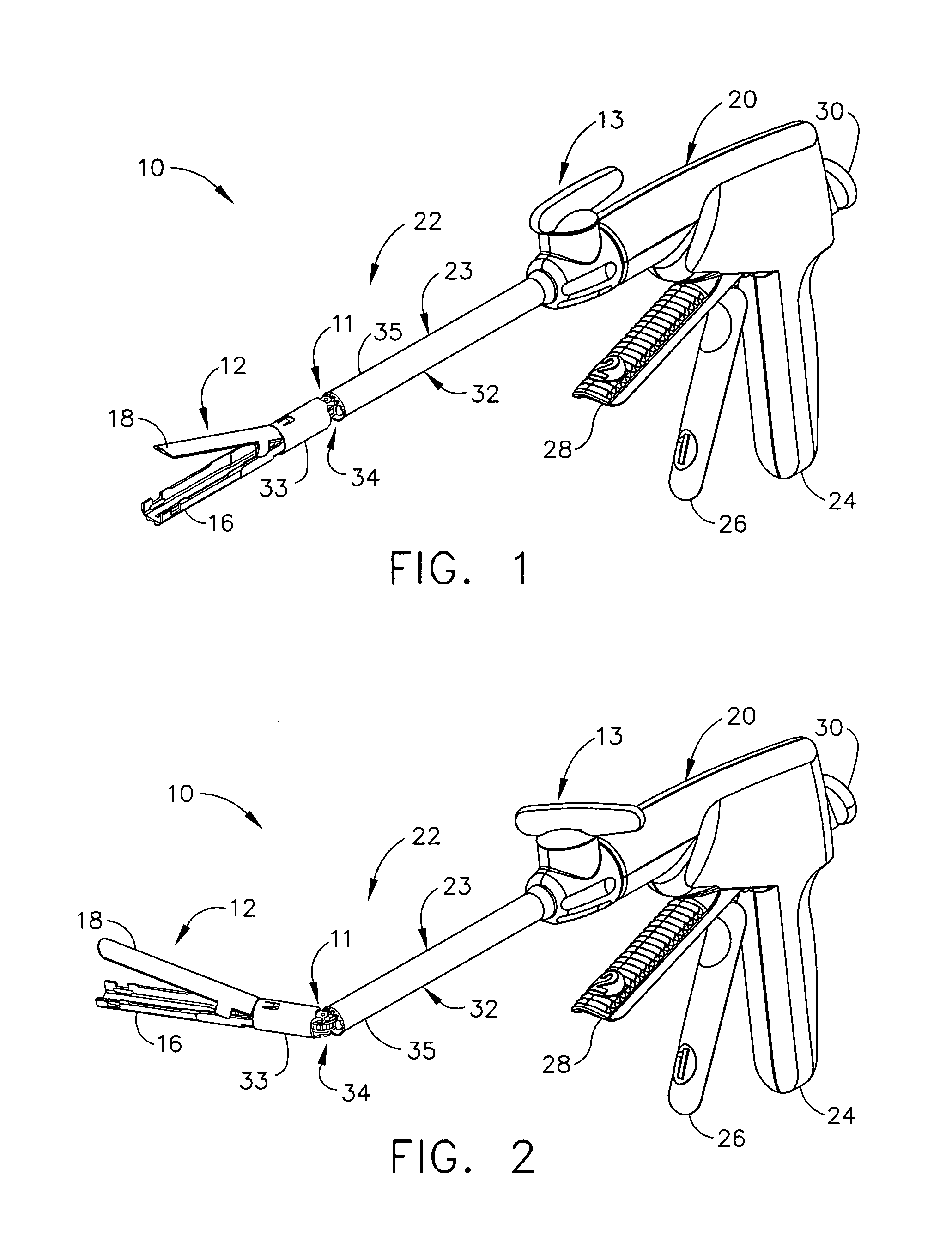
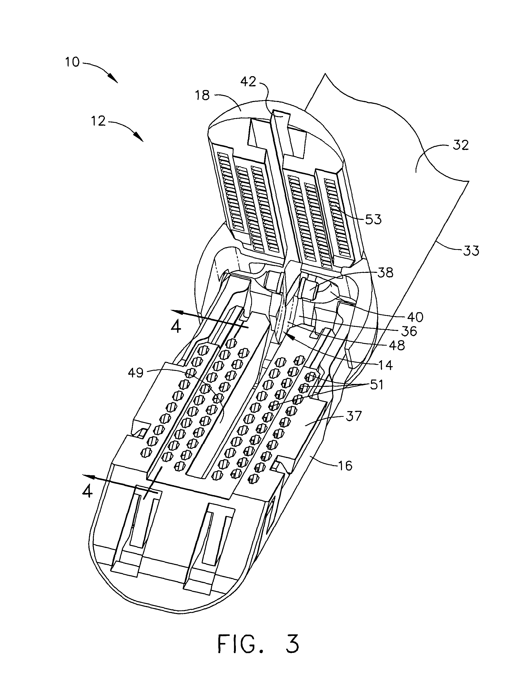
[0034]Turning to the Drawings, wherein like numerals denote like components throughout the several views, FIGS. 1–3 depict a surgical instrument, which in the illustrative embodiment is more particularly a surgical stapling and severing instrument 10, that is capable of practicing the unique benefits of the present invention. In particular, the surgical stapling and severing instrument 10 is sized for insertion, in a nonarticulated state as depicted in FIG. 1, through a trocar cannula passageway to a surgical site in a patient for performing a surgical procedure. Once an articulation mechanism 11 and a distally attached end effector 12 are inserted through the cannula passageway, the articulation mechanism 11 may be remotely articulated, as depicted in FIG. 2, by an articulation control 13. Thereby, the end effector 12 may reach behind an organ or approach tissue from a desired angle or for other reasons. For instance, a firing mechanism, advantageously depicted as an E-beam firing ...


PUM

PropertyMeasurementUnit
angleaaaaaaaaaa
thicknessaaaaaaaaaa
depthaaaaaaaaaa

Abstract

A surgical stapling and severing instrument particularly suited to endoscopic articulates an end effector by having a geared articulation mechanism that converts rotational motion from a handle portion. A firing bar longitudinally translates between the handle portion and the end effector. The firing bar head is thickened in order to present an undistorted cutting edge and engagement features to the opposing jaws of the end effector. The firing bar also advantageously includes a thinned or tapered proximal portion in the form of a strip or band that negotiates the articulation mechanism.

Description

CROSS REFERENCE TO RELATED APPLICATIONS[0001]The present application is related to four co-pending and commonly-owned applications filed on even date herewith, the disclosure of each is hereby incorporated by reference in their entirety, these four applications being respectively entitled:[0002](1) “SURGICAL INSTRUMENT INCORPORATING AN ARTICULATION MECHANISM HAVING ROTATION ABOUT THE LONGITUDINAL AXIS” to Kenneth S. Wales, Douglas B. Hoffman, Frederick E. Shelton IV, and Jeff Swayze;[0003](2) “SURGICAL STAPLING INSTRUMENT INCORPORATING AN ARTICULATION JOINT FOR A FIRING BAR TRACK” to Douglas B. Hoffman;[0004](3) “SURGICAL STAPLING INSTRUMENT HAVING ARTICULATION JOINT SUPPORT PLATES FOR SUPPORTING A FIRING BAR” to Kenneth S. Wales and Joseph Charles Hueil; and[0005](4) “A SURGICAL INSTRUMENT WITH A LATERAL-MOVING ARTICULATION CONTROL” to Kenneth S. Wales.FIELD OF THE INVENTION[0006]The present invention relates in general to surgical stapler instruments that are capable of applying l...

Claims


Application Information

Patent Timeline
Patent Type & Authority Patents(United States)
IPC IPC(8): A61B17/10A61B17/04A61B17/072A61B17/068A61B17/11A61B17/28A61B17/32
CPCA61B17/07207A61B2017/2902A61B2017/320052A61B2017/2932A61B2017/2927
Inventor SHELTON, IV, FREDERICK E.SETSER, MICHAEL EARLWEISENBURGH, II, WILLIAM BRUCE
Owner CILAG GMBH INT
Why Eureka
Try Eureka