Pipe weld cleaning machine

a weld cleaning machine and pipe technology, applied in the field of pipe weld cleaning machines, can solve the problems of time-consuming and labor-intensive cleaning operations, problems such as movement control problems, and the problem of cleaning machines having problems in movement control

Inactive Publication Date: 2006-06-13
SUS SERVICES INT
View PDF15 Cites 24 Cited by
  • Summary
  • Abstract
  • Description
  • Claims
  • Application Information

AI Technical Summary

Problems solved by technology

These previous cleaning machines have had problems in movement control.
As a result, movement control was a problem.
Also, cleaning operations were time consuming and labor intensive.
In addition there were some safety concerns due to the close proximity of some of the work crew to the rotating equipment and supply hoses.

Method used


Image

  • Pipe weld cleaning machine
  • Pipe weld cleaning machine
  • Pipe weld cleaning machine

Examples


Embodiment Construction

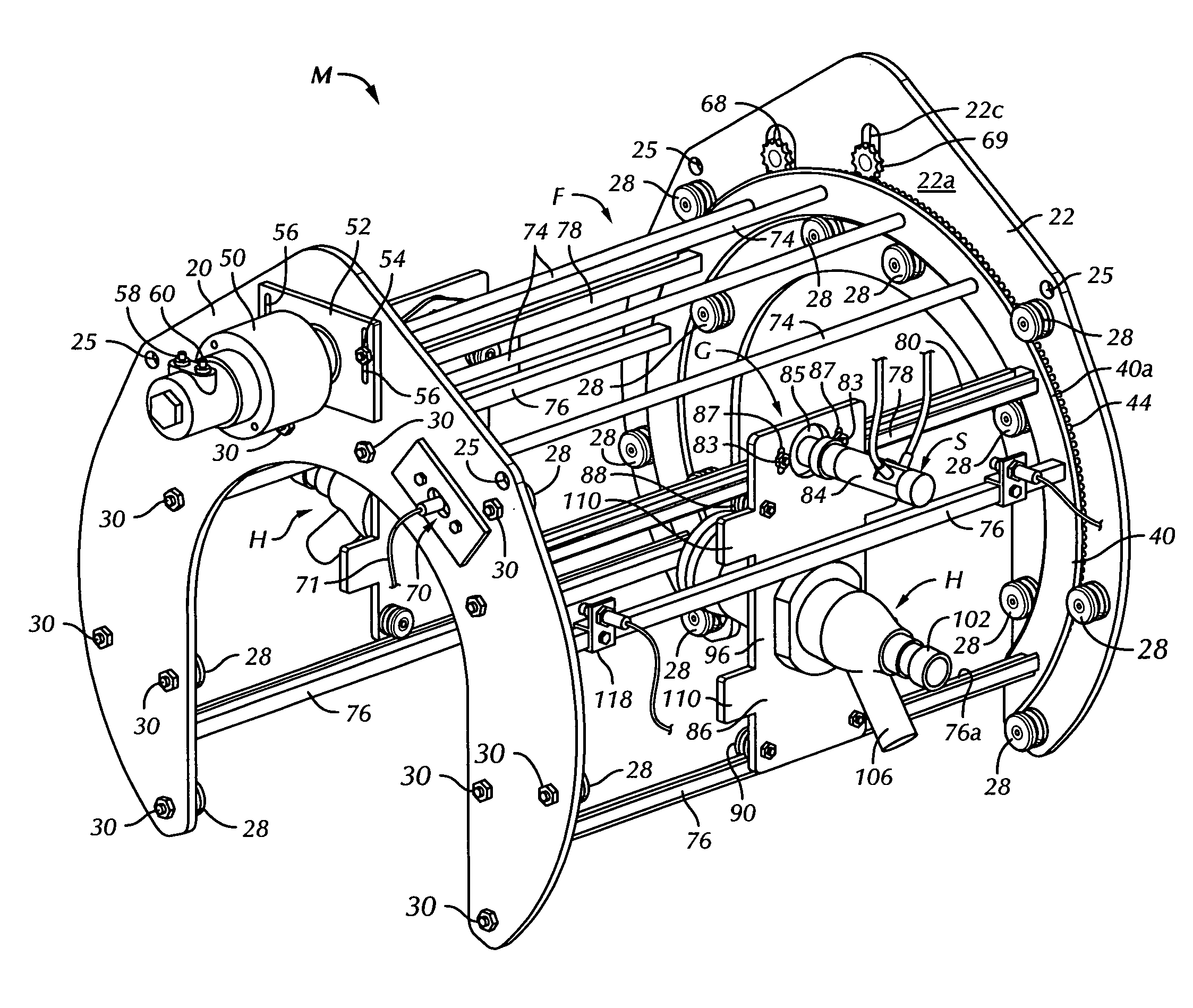
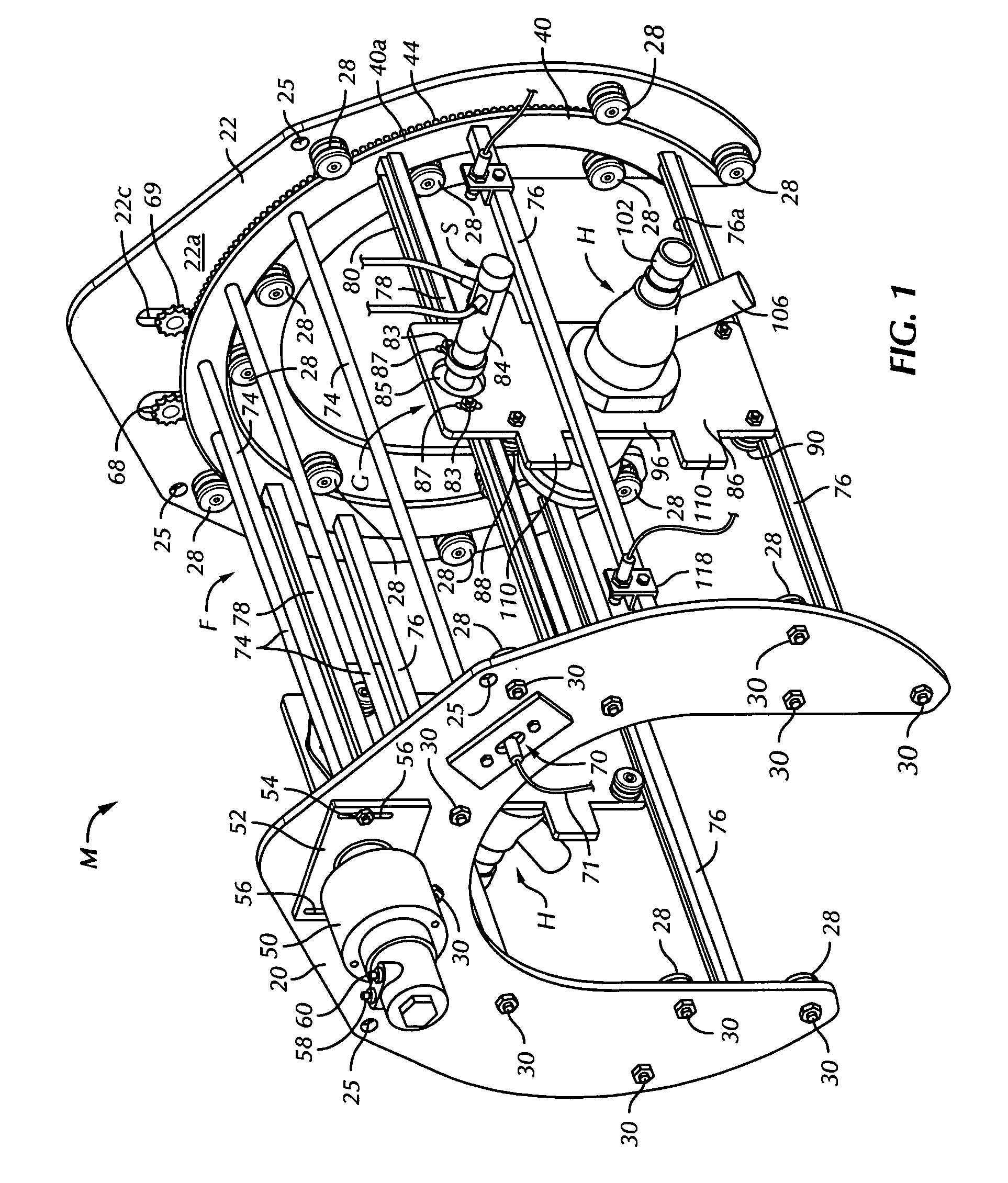
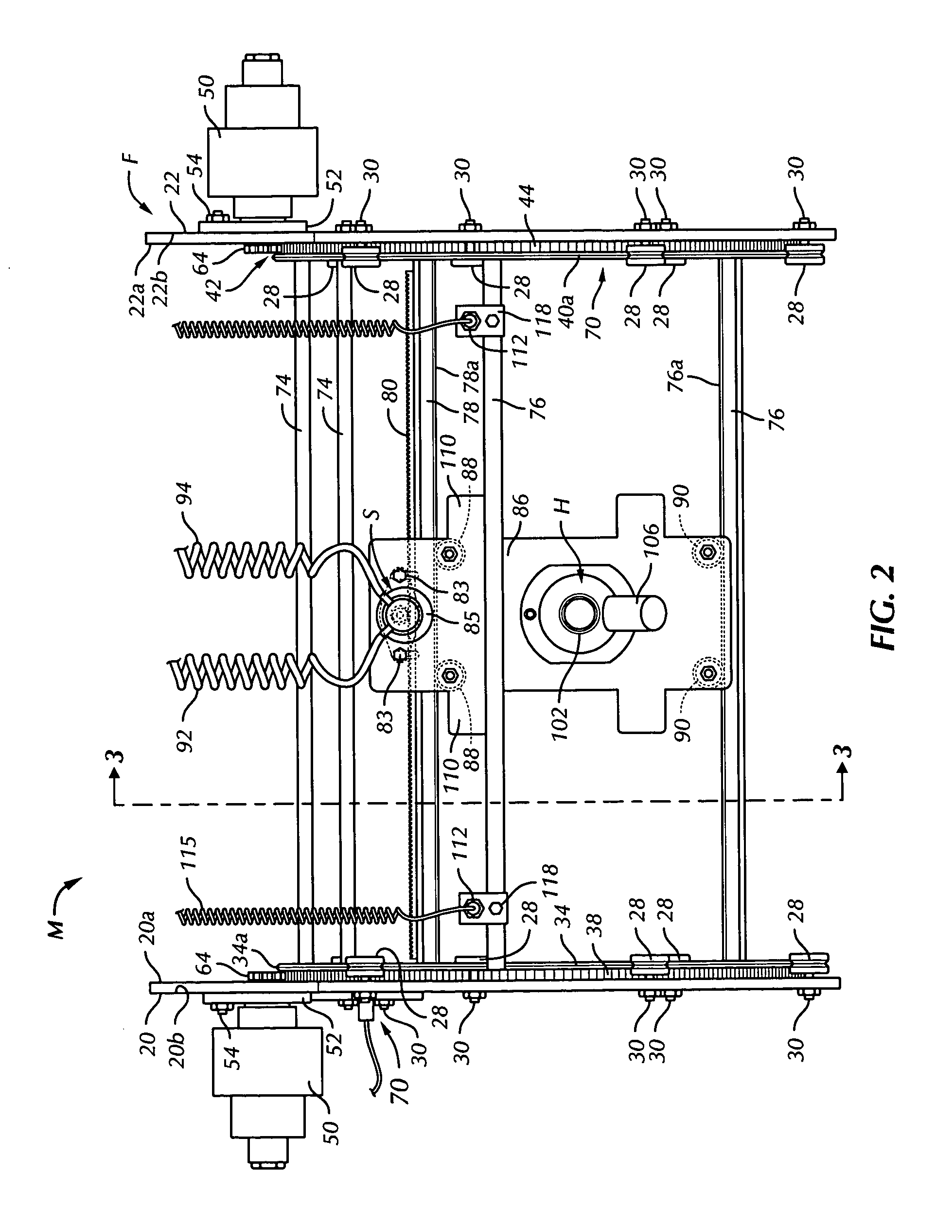
[0020]In the drawings, the letter M (FIGS. 1–3) designates generally a pipe weld cleaning machine according to the present invention. The pipe cleaning machine M is adapted to clean a metal pipe joint J (FIG. 10) formed at end portions 10 and 12 of longitudinally extending joined sections 14 of coated pipe P of the type used in pipelines on or in submerged floors of bodies of water.

[0021]Pipelines have been for a number of years laid on the submerged floors of bodies of water from pipe laying barges. On the pipe-laying barge, the pipeline length was formed by welding end portions 10 and 12 of successive lengths or sections 14 of pipe sequentially in an end-to-end fashion to previously welded sections at an end portion of the pipeline. The pipe section 14 were typically covered with concrete or some other protective coating 14a along their lengths except for the exposed metal end sections 10 and 12. After a length of pipe was welded to the end of the pipeline as indicated at 15, and ...


PUM

PropertyMeasurementUnit
rotational movementaaaaaaaaaa
weightaaaaaaaaaa
lengthaaaaaaaaaa

Abstract

A pipe joint between welded exposed metal end sections of coated pipe being formed into a pipeline is cleaned before a corrosion resistant film is applied. A cleaning head of a cleaning mechanism is placed with a mounting frame on the pipe in the area of the pipe ends to be cleaned. The cleaning head moves in a succession of longitudinal cleaning passes in the direction of the longitudinal axis of the pipe area being cleaned. The frame also moves the cleaning head rotatably with respect to the pipe joint to positions for the longitudinal cleaning passes. A control mechanism defines the extent of the longitudinal cleaning passes, and also controls movement of the cleaning head to successive cleaning passes until the pipe joint is cleaned. The control is programmed and automatic, and there is no need for contact with the mechanism while it is in operation. The number of cleaning heads and cleaning material supply and exhaust hoses or tubes, as well as the number of crew required, is reduced.

Description

BACKGROUND OF THE INVENTION[0001]1. Field of the Invention[0002]The present invention relates to cleaning portions of pipe in the areas where adjacent end sections of pipe have been welded together to form a pipeline or the like. More specifically, the present invention provides a new and improved pipe weld cleaner and control mechanism to regulate and control movement of a cleaning head as it moves along and about the welded pipe end portions while cleaning those end portions after they have been welded together.[0003]2. Description of the Related Art[0004]Pipelines have been for a number of years laid on the submerged floors of bodies of water from pipe laying barges. On the pipe-laying barge, the pipeline length was formed by welding successive lengths or sections of pipe sequentially in an end-to-end fashion to previously welded sections at an end portion of the pipeline. The pipe sections were typically covered with concrete or some other protective coating along their lengths ...

Claims


Application Information

Patent Timeline
Patent Type & Authority Patents(United States)
IPC IPC(8): B08B9/02B24C1/08B24C3/06B24C3/32
CPCB24C1/08B24C3/32B24C3/06B08B9/021
Inventor SKINNER, DONALD P.
Owner SUS SERVICES INT
Why Eureka
Try Eureka