

Adjustable tensioning system for rimless eyewear
a tensioning system and rimless technology, applied in the field of eyewear frames, can solve the problems of true rimless eyewear, unrecoverable cost, and high cost of fashionable eyewear, and achieve the effects of small tolerance, correct tautness or tension, and reduced cos
- Summary
- Abstract
- Description
- Claims
- Application Information
AI Technical Summary
Benefits of technology
Problems solved by technology
Method used
Image

Examples
Embodiment Construction
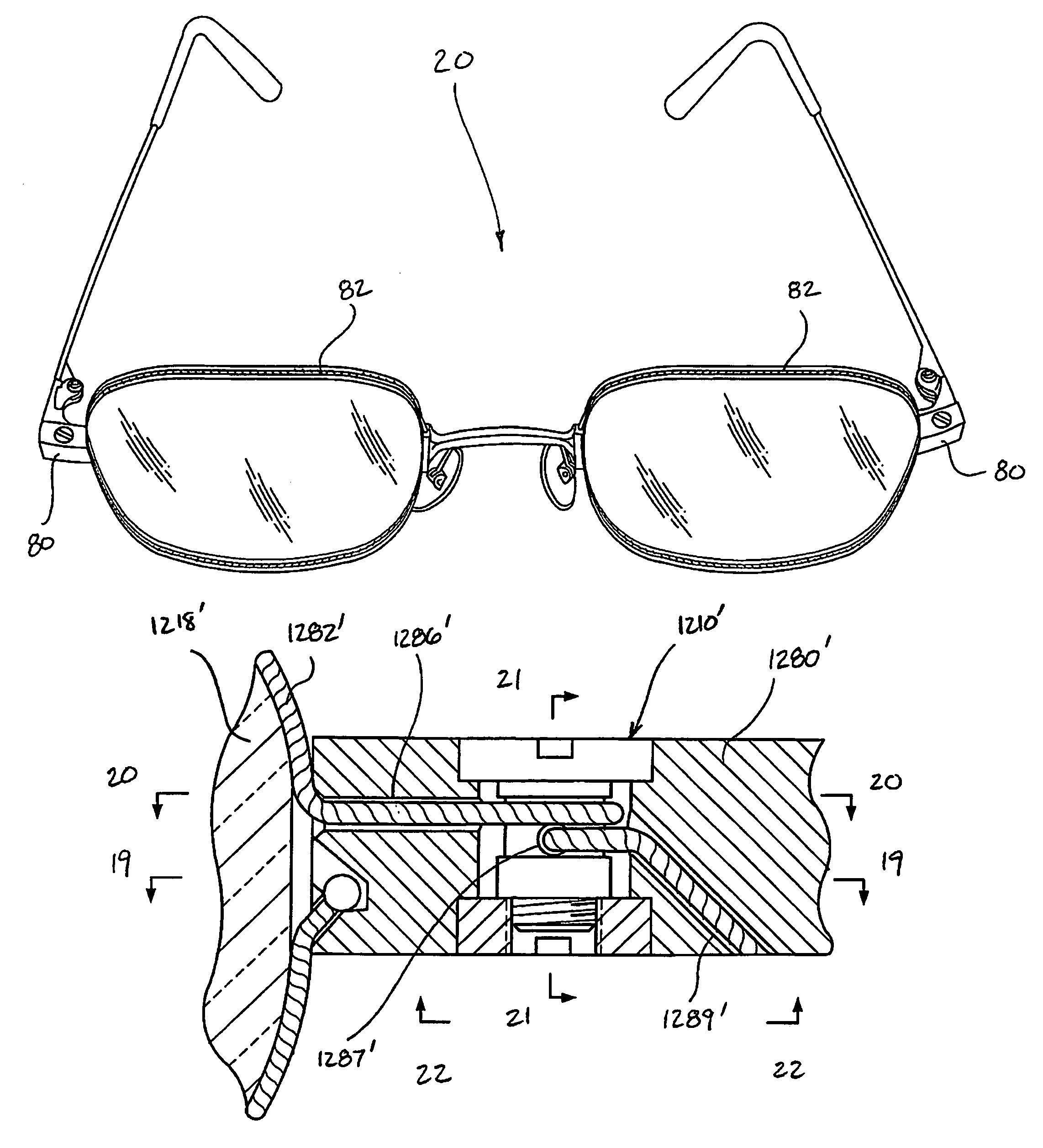
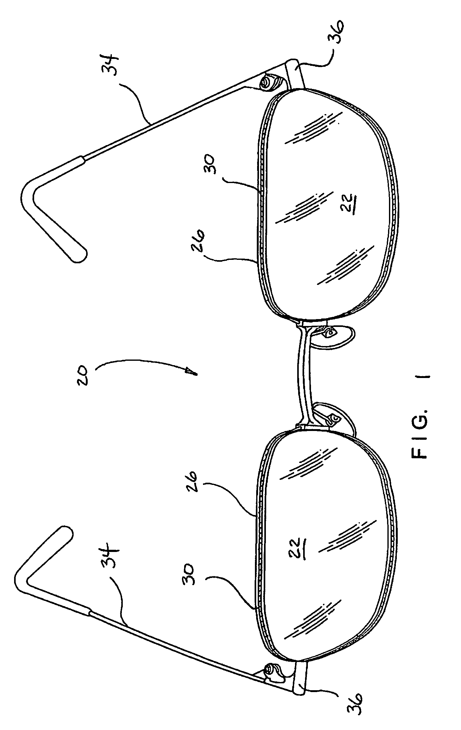
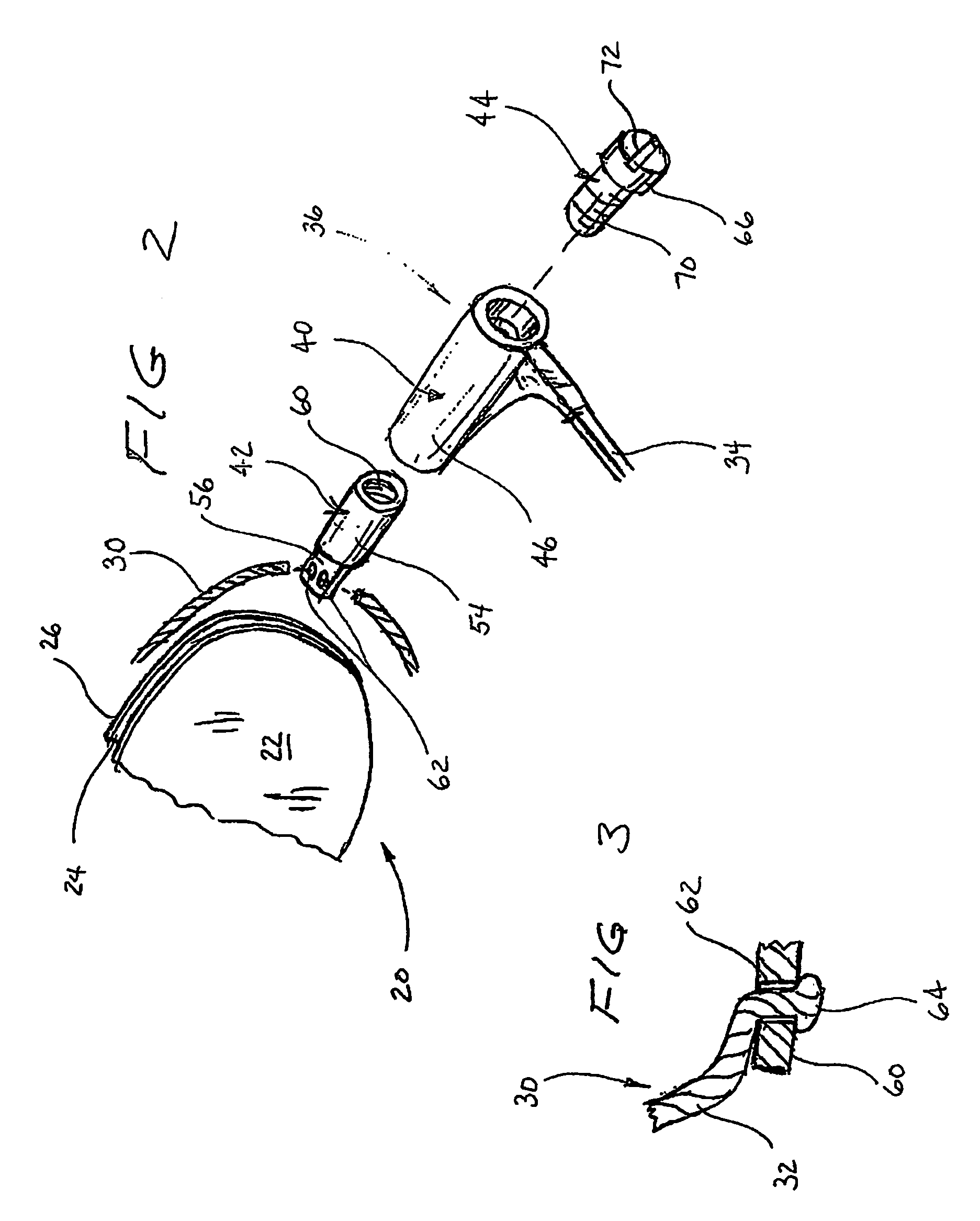
[0061]The present invention generally relates to eyewear frame assemblies that feature a flexible cable or a wire that substantially encircles each lens such that the lens can be secured in position within a loop defined by the cable or the wire. Examples of such eyewear are shown and described in copending U.S. patent application Ser. No. 10 / 678,964, filed on Oct. 2, 2003, U.S. patent application Ser. No. 10 / 610,862, filed on Jun. 30, 2003, U.S. patent application Ser. No. 10 / 269,811, filed on Oct. 11, 2002, and U.S. Provisional Patent Application No. 60 / 394,837, filed on Jul. 10, 2002, which references are hereby incorporated by reference in their entirety. Copending U.S. patent application Ser. No. 10 / 846,357, filed concurrently herewith, entitled Eyeglass Frame Assembly and copending U.S. patent application Ser. No. 10 / 846,953 filed concurrently herewith, entitled Adjustable Tensioning System for Rimless Eyewear and also are hereby incorporated by reference in their entirety.
[00...
PUM
 Abstract
Description
Claims
Application Information