
Adjustable tensioning system for rimless eyewear

a technology of tensioning system and rimless eyewear, which is applied in the direction of spectacles/goggles, instruments, spectacles/goggles, etc., can solve the problems of increasing the ultimate cost of eyewear for consumers, the lens has to be discarded, and the mechanical structure used to support the lens and the lens is visible overlap, etc., to achieve the effect of reducing the movement of components, and reducing the risk of eye injury

Inactive Publication Date: 2007-11-22
LERNER IRA S +1
View PDF75 Cites 0 Cited by
  • Summary
  • Abstract
  • Description
  • Claims
  • Application Information

AI Technical Summary

Benefits of technology

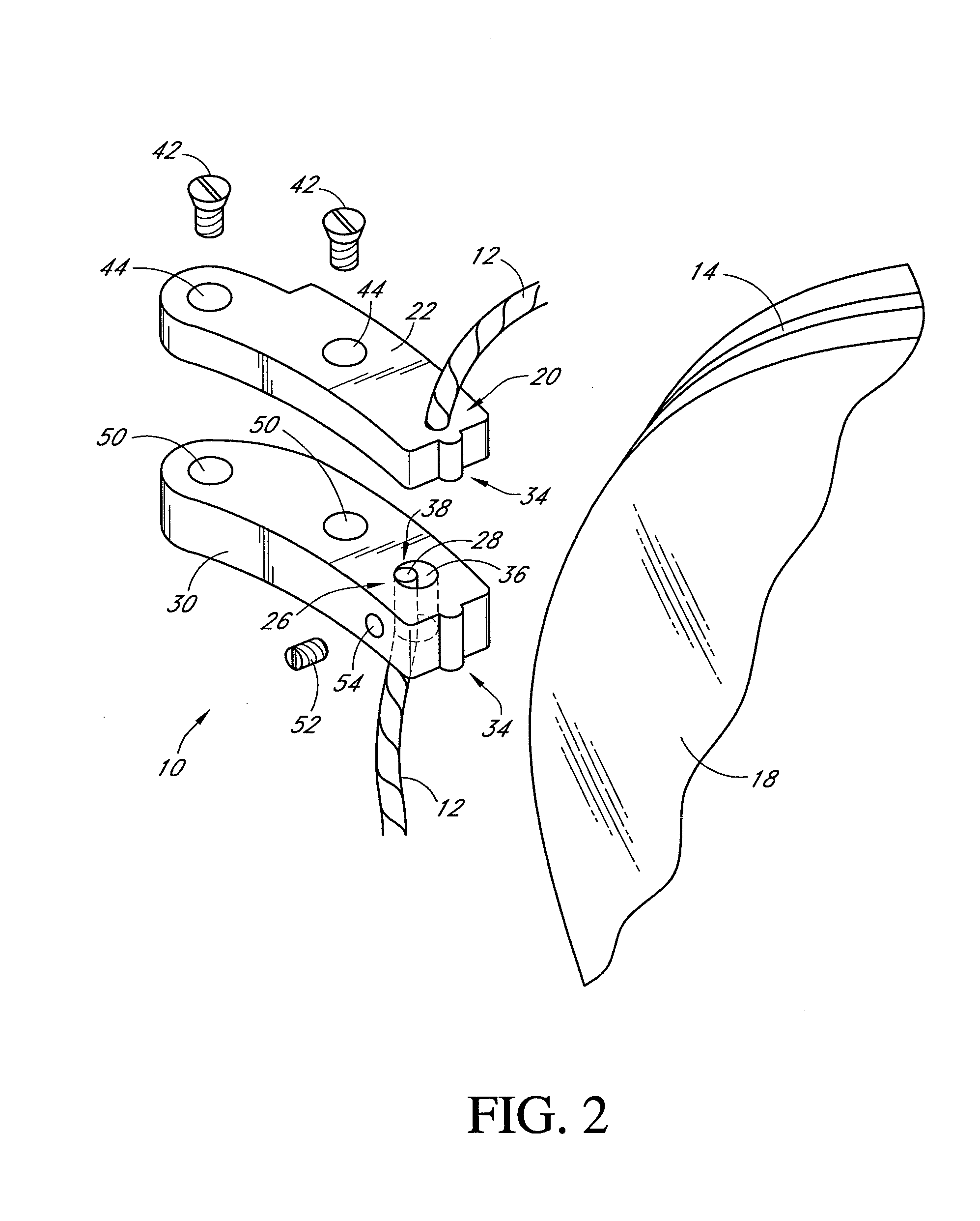
[0007] The constructions described in the co-pending application generally require the wire to be sufficiently taut such that undesired movement of the components can be minimized or eliminated. The correct tautness or tension is achieved in many of these constructions only when the lenses are cut to the proper shape and size within very small tolerances. Given variations in the calibration and measuring systems of individual lens cutting equipment, and allowances for variations by the optical technicians using the equipment, this style of rimless eyewear admits to some improvements such that secure and practical rimless eyewear can be manufactured.
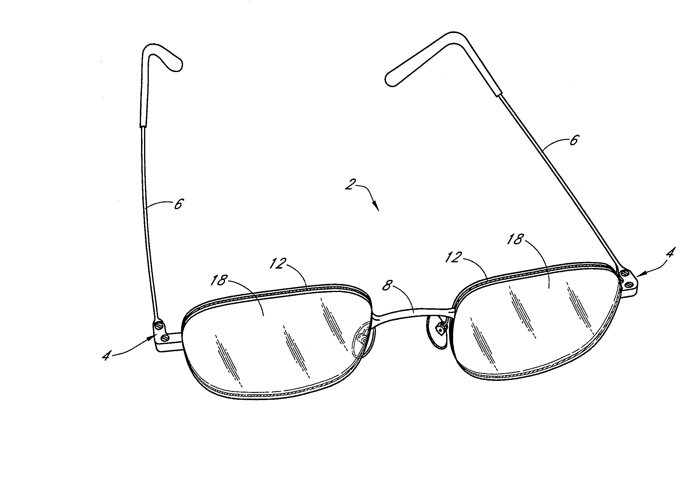
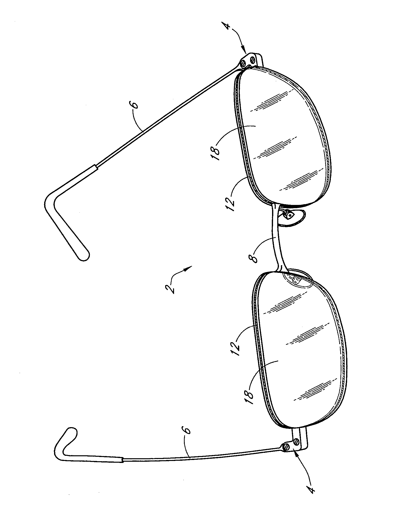
[0008] While various systems for adjustment and tensioning of the wire can be envisioned, it is preferred that the adjustment system have an exterior configuration that closely resembles a standard endpiece. Such a construction would minimize the visual prominence of the adjustment system. Moreover, such a construction would minimize any overlap of the lens by the system such that the prominence of the mounting structure can be reduced and the eyewear can become even more transparent to observers of the user of the eyewear.

Problems solved by technology

Such arrangements result in a visible overlap of the mechanical structures used to support the lenses and the lenses themselves.
Moreover, when preparing the lenses or when mounting the mechanical structures to the frames, the lenses are prone to chipping and cracking, which results in the lenses having to be discarded and increase the ultimate cost to the consumer of the eyewear.
In addition, these mounting systems require highly precise drilling of holes, notches, etc., such that costly and time consuming outside lens preparation services are often required.

Method used


Image

  • Adjustable tensioning system for rimless eyewear
  • Adjustable tensioning system for rimless eyewear
  • Adjustable tensioning system for rimless eyewear

Examples


Embodiment Construction

[0048] The present invention generally relates to eyewear frame assemblies featuring a flexible wire that forms at least a major portion of a lens securing frame. In some arrangements, the flexible wire generally circumscribes the associated lens. To provide a generic frame assembly that is capable of providing customizable lens shapes and sizes, the wire can have a length sufficient to extend around a lens and can be tightened about the lens such that lenses of varied sizes and shapes can be secured within a single frame assembly. In all of the embodiments described herein, each lens can comprise a tinted lens, a corrective lens or any other desired type of lens, including but not limited to a protective lens.

[0049] Preferably, the wire extends around at least about 90% of the circumference of the associated lens. In some embodiments, the wire extends around at least about 95% of the circumference of the associated lens. In other embodiments, the wire extends almost entirely or en...


PUM


Abstract

Rimless eyewear features a wire that encircles a lens. Systems are provided for selectively increasing or decreasing a tensile load on the wire to facilitate assembly and maintenance of the eyewear. An adjusting screw, different wire securement positions, and / or adjustment shims provide easy tension adjustment of the wire and secure the eye lens in a predetermined position and orientation.

Description

CROSS-REFERENCE TO RELATED APPLICATIONS [0001] This application is a divisional of and claims priority benefit under 35 U.S.C. § 120 from U.S. patent application Ser. No. 10 / 846,953, filed May 14, 2004, which is incorporated in its entirety by reference herein and made a part of this specification.BACKGROUND OF THE INVENTION [0002] 1. Field of the Invention [0003] The present invention relates generally to an adjustable lens securing system for rimless eyewear, and more particularly to an adjustable tensioning system that allows easy assembly and adjustment of a wire used to secure at least one eye lens. [0004] 2. Description of the Related Art [0005] Recently, developments in the eyewear industry have resulted in the creation of eyewear in which the lenses appear to be unattached to any frame. Such eyewear is being called “rimless.” Temples and a bridge can be secured to the lenses with fasteners that extend through the lenses or with clamps that clamp over a portion of the lenses....

Claims


Application Information

Patent Timeline
Patent Type & Authority Applications(United States)
IPC IPC(8): G02C5/00G02C1/02G02C1/04G02C1/08
CPCG02C1/02G02C2200/10G02C5/008
Inventor LERNER, IRA S.PILAT, JAMES F. JR.
Owner LERNER IRA S
Learn More