Quick coupler anchor

a coupler and anchor technology, applied in the direction of machine supports, transportation and packaging, thin material processing, etc., can solve the problems of significant injury potential, device not particularly stable, valve may disconnect from the supply pipe, etc., to achieve the effect of reducing or eliminating the rotational movement of the valv

Active Publication Date: 2005-03-31
HARCO FITTINGS LLC
View PDF10 Cites 0 Cited by
  • Summary
  • Abstract
  • Description
  • Claims
  • Application Information

AI Technical Summary

Benefits of technology

[0007] In a preferred embodiment according to the present invention, there is provided apparatus for restraining movement of a valve embedded in the ground, comprising an anchor for securement to the valve and including an anchor body for disposition in the ground and having at least first and second plates spaced from one another and extending generally vertically in discrete planes non-parallel to one another and which planes, when extended, intersect one another along a generally vertical line and a connecting member carried by the anchor body connecting the plates to one another and engageable with the valve to substantially minimize or eliminate rotational movement of the valve relative to the anchor in response to a torque applied to the valve to open or close the valve.
[0008] In a further preferred embodiment according to the present invention, there is provided an in-ground irrigation system, comprising a valve having a central vertical axis and threaded onto a pipe about the vertical axis, the valve including a valve body having a plurality of flats about the axis, an anchor for securement to the valve and including an anchor body disposed in the ground and extending at least partially about the valve, the anchor body including first and second plates spaced from one another and extending generally vertically in discrete planes non-parallel to one another and which planes, when extended, intersect one another along a generally vertical line laterally offset from the axis and a connecting member carried by the anchor body connecting the plates to one another and engaged with the valve, the anchor body including a recess having a plurality of angularly-related flats facing inwardly towards and engaging the flats of the valve body to substantially preclude rotation of the valve relative to the anchor body in response to a torque applied to the valve to open or close the valve.

Problems solved by technology

When rotating the bayonet connector, however, the applied torque tends to rotate the valve relative to the supply pipe.
As a consequence, the joint between the valve and supply pipe unthreads, causing leakage and, over time and with sufficient use, the valve may disconnect from the supply pipe.
In the latter event, the valve can pop off the supply pipe with considerable force due to the high water pressure in the supply pipe and hence there arises a significant potential for injury.
However, such devices do not appear to be particularly stable.
This lack of coincidence of the vertical forces introduces a moment arm tending to tilt the valve and / or anchor upon application of the vertical force and hence renders the system unstable.

Method used


Image

  • Quick coupler anchor
  • Quick coupler anchor
  • Quick coupler anchor

Examples


Embodiment Construction

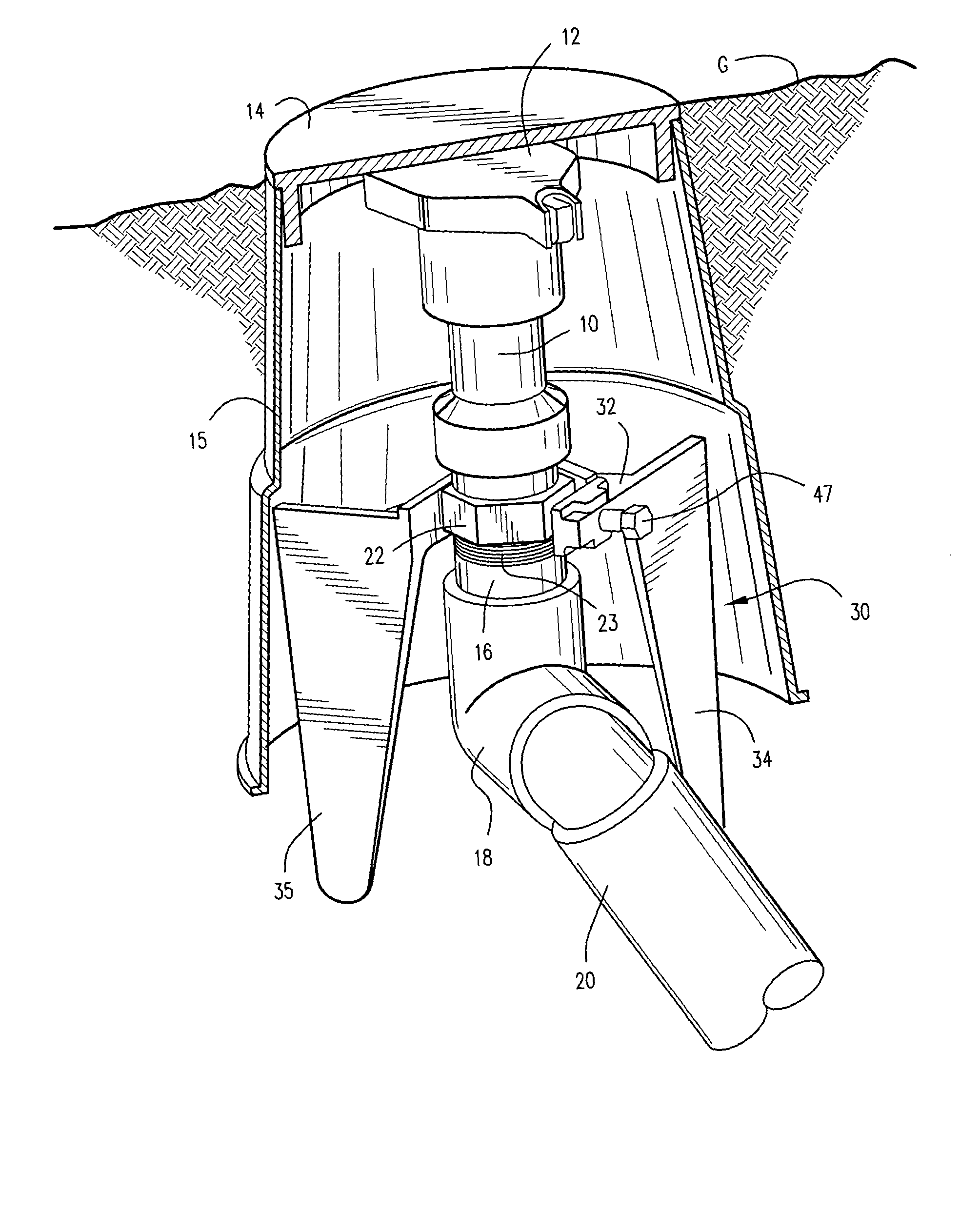
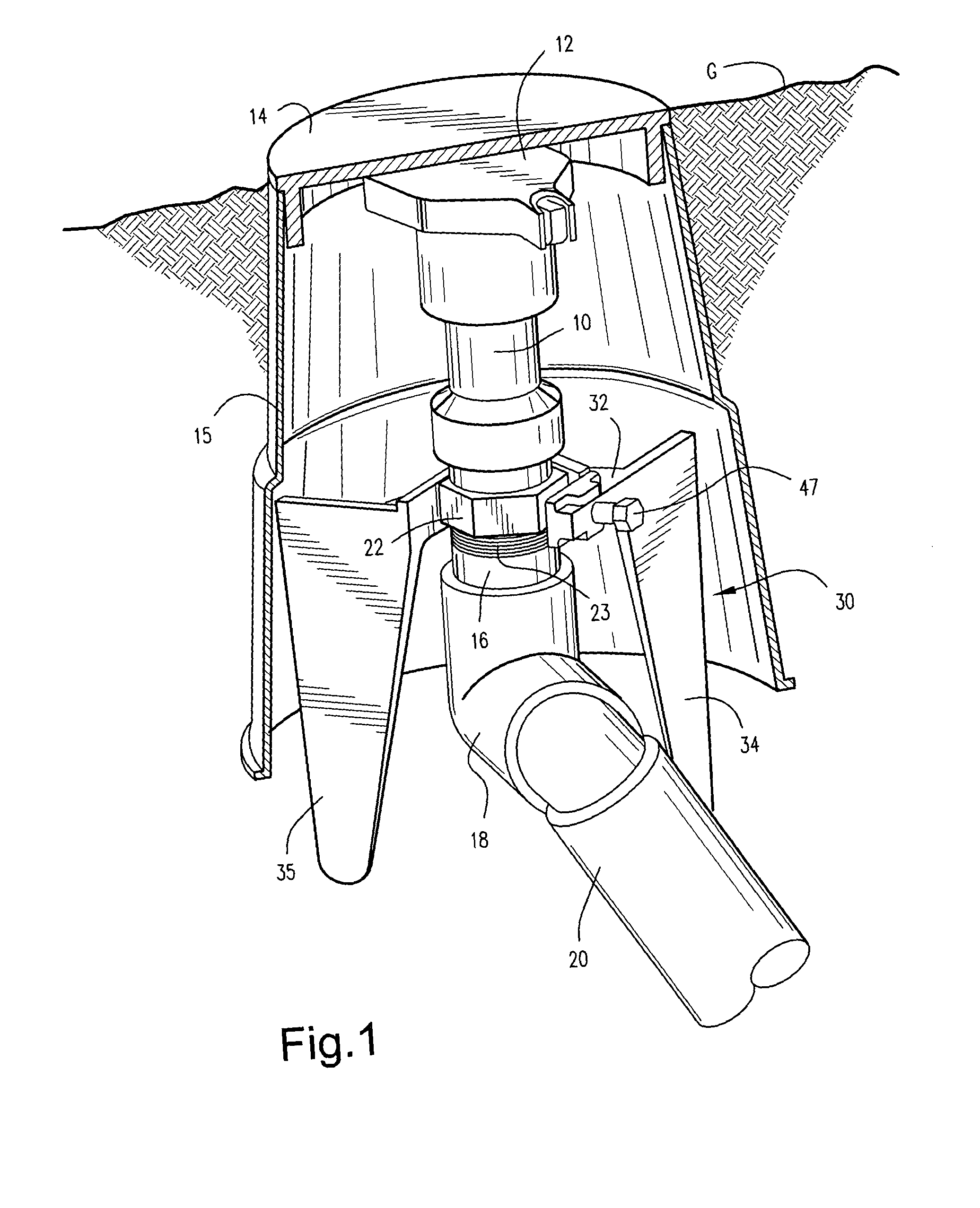
[0013] Referring now to FIG. 1, there is illustrated an underground fluid, e.g., water, distribution supply system, including a valve 10 disposed underground and terminating at its upper end in a pivoted valve cap 12. The valve cap 12 is, in turn, overlaid with a cover 14 lying generally flush at ground level G, the cover 14 forming part of a valve box 15 encapsulating valve 10. The valve 10 at its lower end is screwthreaded into a vertical pipe section 16, which, in turn, and through the use of an elbow 18, is coupled to a branch pipe 20. Branch pipe 20 may be connected to a main supply pipe, not shown, whereby water under pressure, is supplied to the valve 10. As illustrated, the lower portion of the valve 10 terminates in a hex nut 22 having female threads for threaded engagement with the male threads 23 on the pipe 16. As noted above, the valve 10, with the cover 14 removed and cap 12 pivoted back to expose the valve, is capable of receiving a conventional bayonet-type connector...


PUM


Abstract

The quick coupler anchor includes an anchor body having a pair of vertical plates extending generally at right angles one to the other and spaced from one another. Planes containing the plates, when extended, intersect along a vertical line offset from the center axis of a valve received in a recess in a member connecting upper edges of the vertical extending plates. The recess has a plurality of flats for registration with the flats of the hex nut of the valve body. When the anchor is embedded in the ground with the recess about the hex nut, the anchor restrains rotational movement of the valve relative to the anchor in response to a torque applied to the valve to open or close the valve. The center of vertical support of the anchor lies generally coincident with the vertical axis of the valve to provide stability to the valve and anchor upon vertical loadings.

Description

BACKGROUND OF THE INVENTION [0001] The present application relates to a quick coupler anchor for engaging the valve of an underground fluid, e.g., water, supply system, and particularly relates to an anchor for restraining rotation of the valve relative to its connection with the underground fluid supply system when a torque is applied to the valve to open or close the valve and more particularly to an anchor which affords stability to the system under multi-directional loadings. [0002] In underground water supply systems, for example, for irrigating golf courses, a water distribution supply pipe extends vertically below-ground and is coupled at its lower end to a main or branch water distribution pipe. The opposite end of the vertically disposed distribution pipe is threadedly coupled with a valve which terminates substantially flush with ground level. The valve has a cap and a cover typically overlies the cap. To open the valve and, hence, supply water to an above-ground distribut...

Claims


Application Information

Patent Timeline
Patent Type & Authority Applications(United States)
IPC IPC(8): F16L3/00
CPCF16L3/003Y10T137/6991
Inventor RIORDAN, JOHN EMMETT IIIROUTON, SEAN BRIAN
Owner HARCO FITTINGS LLC
Why Eureka
Try Eureka