Cartridge case with chip retaining features

a cartridge case and chip technology, applied in the field of magnetic tape cartridges, can solve the problems of often failing to properly pick up the cartridge memory by suction means, and achieve the effect of preventing a downward displacement of the cartridge memory

Inactive Publication Date: 2006-06-20
FUJIFILM CORP +1
View PDF4 Cites 9 Cited by
  • Summary
  • Abstract
  • Description
  • Claims
  • Application Information

AI Technical Summary

Benefits of technology

[0021]With such a constitution of the cartridge case, when the upper half is assembled with the lower half after respective constituent parts are assembled onto the lower half, the stopper member reaches the cartridge memory-rising region indicating a spatial region where the cartridge memory obliquely retained on the lower half would possibly rise, before the constituent parts contact with the upper half. Therefore, even in the case that any of the constituent parts contacts with the supporting members of the upper half and vibration and impact occurs, rising of the cartridge memory is prevented by the stopper member, and if the cartridge memory is about to rise, it will fall down to the original position. Accordingly, it is possible to assemble the cartridge memory in the same predetermined retaining state, and thereby preventing defective assembly of the cartridge memory.
[0044]With such an assembling device, since the sucking means sucks and picks up the cartridge memory at its flat portion, defective pick-up or suction of the cartridge memory is prevented between the sucking means and the flat portion of the cartridge memory, which ensures suction of the cartridge memory. Furthermore, since the sucking tube of the suction means is in the form of a long thin tube, even if the suction means tilts at the time of obliquely assembling the cartridge memory with the lower half of the cartridge case, it is possible to prevent contacts between the sucking tube and the reel.

Problems solved by technology

Therefore, the suction means often fails to pick up the cartridge memory properly.

Method used


Image

  • Cartridge case with chip retaining features
  • Cartridge case with chip retaining features
  • Cartridge case with chip retaining features

Examples


first embodiment

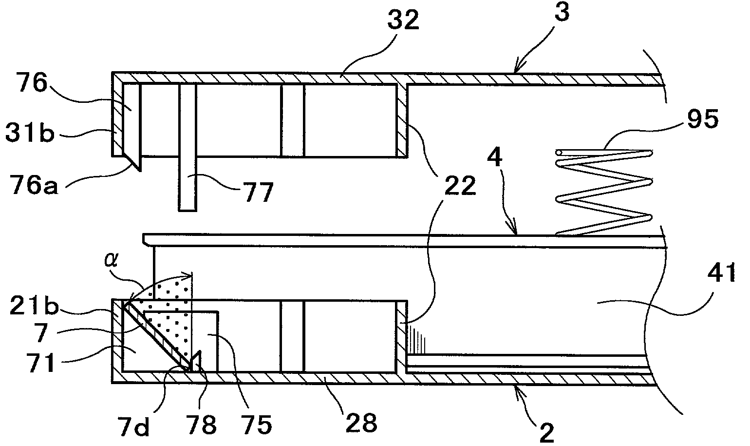
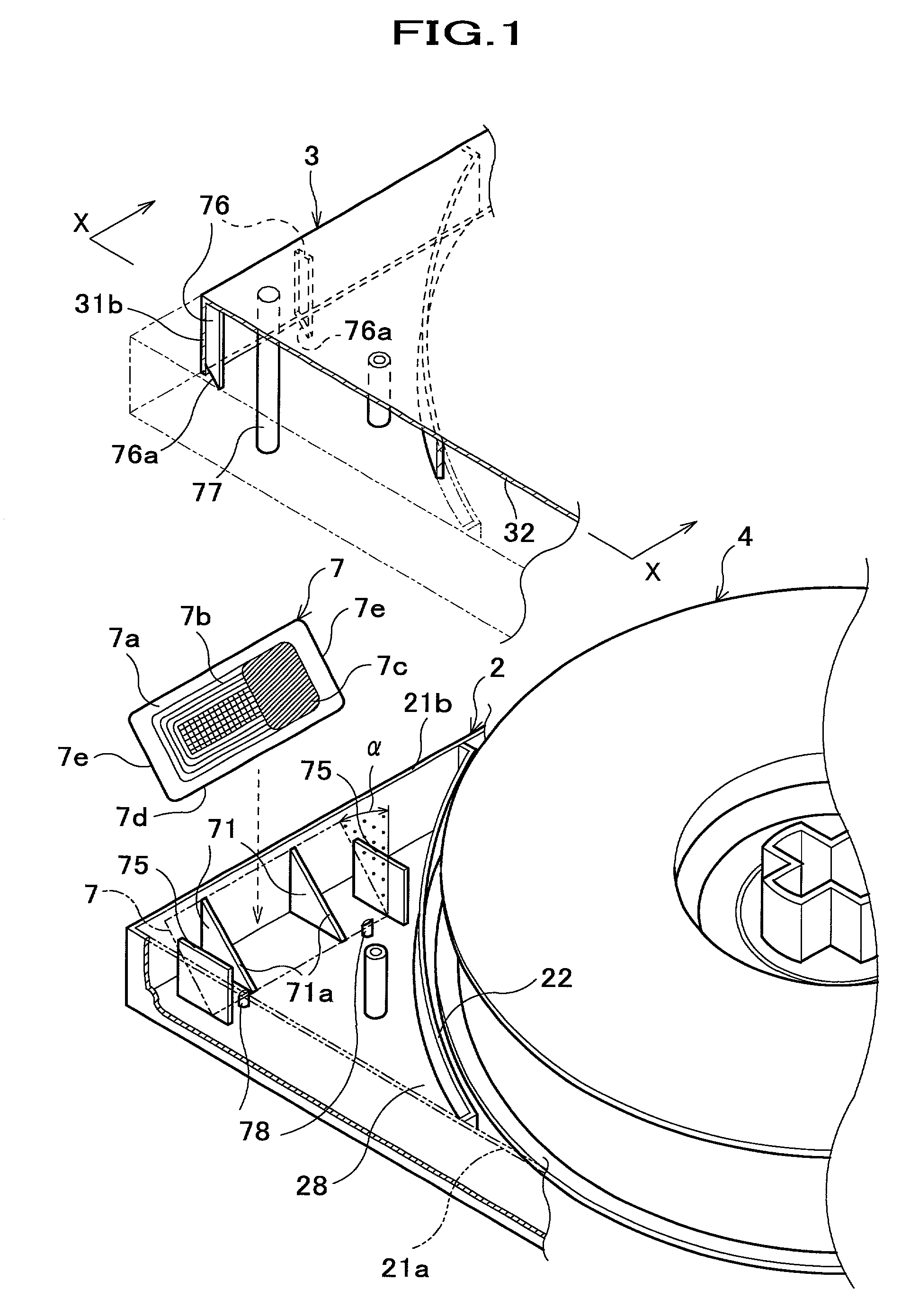
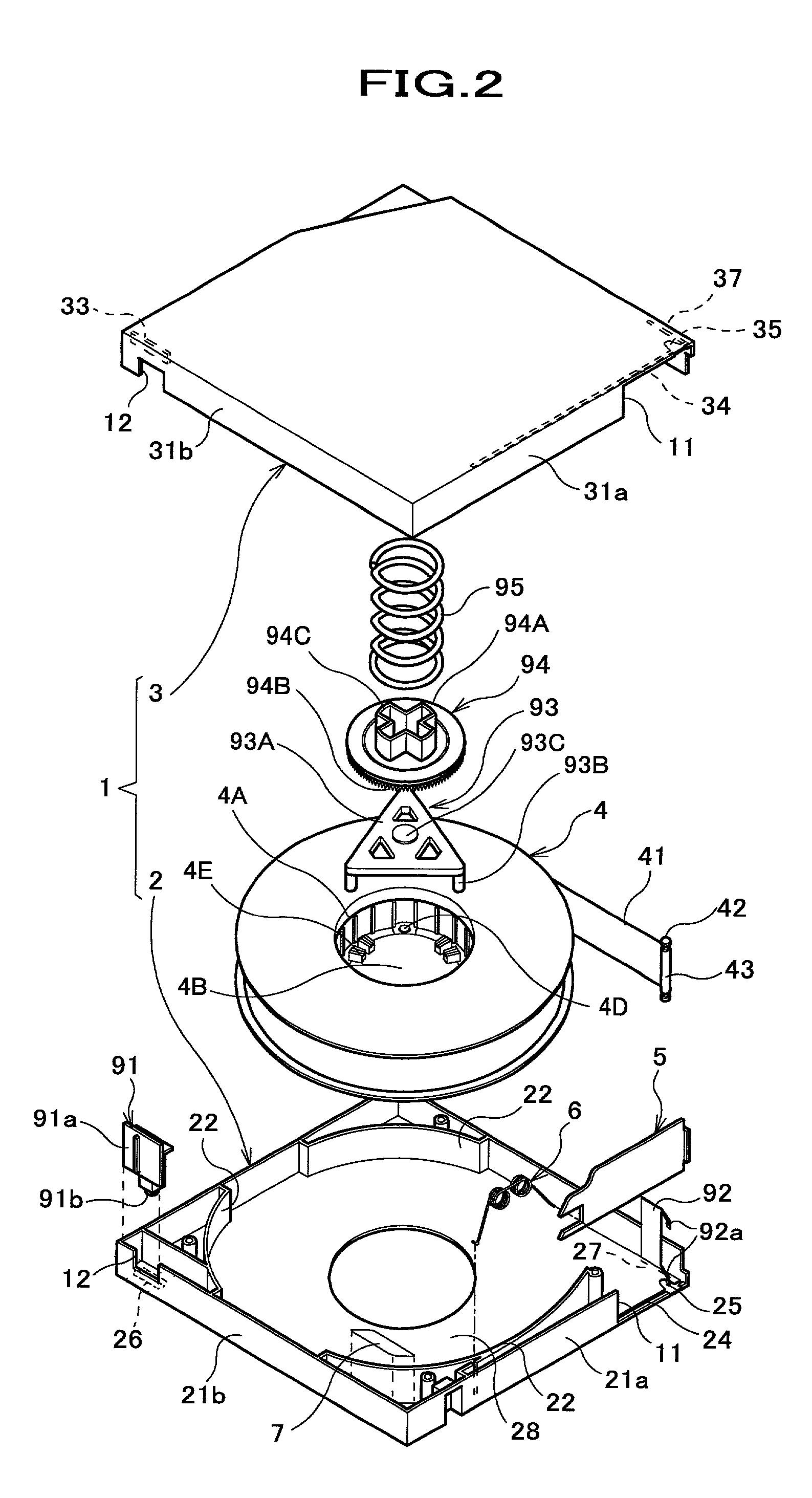
[0065]A first embodiment of the present invention will be described with reference to the drawings. As the drawings to be referred herein, FIG. 1 is an enlarged exploded perspective view of a magnetic tape cartridge, partly illustrating structure where a cartridge memory is assembled, and FIG. 2 is an exploded perspective view illustrating one example of a magnetic tape cartridge which satisfies LTO standard.

[0066]The whole structure of a magnetic tape cartridge, which satisfies LTO standard, will be described with reference to FIG. 2. As shown in FIG. 2, the magnetic tape cartridge includes a cartridge case 1 consisting of a lower half 2 and an upper half 3, and within the cartridge case 1, a reel 4 around which a magnetic tape 41 is wound, a slide door 5, a torsion coil spring 6, a cartridge memory 7, a safety lug 91, a thin plate spring 92, a release pad 93, a lock plate 94, and a compression coil spring 95 are accommodated.

[0067]At a corner of one side wall of the cartridge case...

second embodiment

[0095]A second embodiment of the present invention will be described with reference to the drawings. As the drawings to be referred herein, FIG. 5 is an enlarged exploded perspective view partly illustrating a lower half, a cartridge memory, and a weight member of a cartridge case according to a second embodiment of the invention. Since the overall construction of the magnetic tape cartridge is substantially the same as that of the first embodiment, parts similar to those previously described with respect to the first embodiment are denoted by the same reference numerals and detailed description thereof will be omitted.

[0096]In the magnetic tape cartridge shown in FIG. 5, two projections 78 engagable with the lower side 7d of the cartridge memory 7 are formed on the bottom plate 28, and the lower side 7d of the cartridge memory 7 is positioned by the retaining slanted surface 71a and the projections 78. Further, in order to prevent the cartridge memory 7 from sliding along its lower...

third embodiment

[0103]A third embodiment of the present invention will be described. FIG. 7 is an enlarged exploded perspective view partly illustrating a lower half, a cartridge memory, and a weight member of a cartridge case according to a third embodiment of the invention. In this embodiment, parts similar to those previously described with respect to the first and the second embodiments are denoted by the same reference numerals and detailed description thereof will be omitted.

[0104]In this embodiment, modifications are shown with regard to the second embodiment, in which the weight member is modified and other members supporting the lower side 7d of the cartridge memory 7 is also modified in accordance with the modified weight member.

[0105]As shown in FIG. 7, the lower side 7d of the cartridge memory 7 is supported by an engaging rib 78a extending linearly along the line connecting the bottom ends of the pair of retaining slanted surfaces 71 a and having a predetermined length and a height sub...


PUM

PropertyMeasurementUnit
angleaaaaaaaaaa
inclination angleaaaaaaaaaa
angleaaaaaaaaaa

Abstract

A cartridge case 1 for a magnetic tape cartridge comprises a cartridge case 1 consisting of a lower half 2 and an upper half 3. The lower half 2 is provided with retaining ribs 71 each having a retaining slanted surface 71a such that a plate-like cartridge memory 7 is positioned on the retaining slanted surfaces 71a with its one side 7d lowered and is obliquely supported with respect to a bottom plate 28 of the lower half 2. The upper half 3 is provided with supporting members for supporting various non-resilient constituent parts positioned on the lower half 2 and including the cartridge memory 7. The upper half 2 is provided with a stopper rod 77 such that when the upper half 3 is assembled with the lower half 2, the stopper rod 77 reaches a cartridge memory-rising region before the supporting members contact with the non-resilient constituent parts on the lower half 2.

Description

FIELD OF THE INVENTION[0001]The present invention relates to a magnetic tape cartridge wherein a cartridge case consisting of an upper half and a lower half accommodates therein a non-contacting type memory (hereinafter referred to as a cartridge memory) in a slanted manner, and more particularly relates to technique improving assembling characteristics of the magnetic tape cartridge.BACKGROUND OF THE INVENTION[0002]In recent years, magnetic tape cartridges have been provided with a cartridge memory, which stores management information inherent in the cartridge, such as contents stored in the magnetic tape cartridge, kinds of magnetic tape cartridges, etc. Since such a cartridge memory is capable of transmitting and receiving electric power or signals with electromagnetic induction in a non-contacting manner, it is accommodated in the cartridge case of the magnetic tape cartridge.[0003]Of these magnetic tape cartridges provided with a cartridge memory, and especially magnetic tape c...

Claims


Application Information

Patent Timeline
Patent Type & Authority Patents(United States)
IPC IPC(8): G11B23/02G11B23/087G11B23/107G11B23/113G11B23/30
CPCG11B23/113G11B23/08714
Inventor KITAMURA, KOUTATSUYUKI, SEIJIYAMAMOTO, HIDETOSHIISHIHARA, YUSUKE
Owner FUJIFILM CORP
Why Eureka
Try Eureka