Connector

a technology of connectors and connectors, applied in the direction of connection, electrical apparatus, coupling device connection, etc., can solve the problems of poor assembly workability and disclosed connector structure, and achieve the effect of improving assembly workability and preventing defective assembly

Active Publication Date: 2020-06-30
YAZAKI CORP
View PDF22 Cites 4 Cited by
  • Summary
  • Abstract
  • Description
  • Claims
  • Application Information

AI Technical Summary

Benefits of technology

[0007]The present invention has been made in view of the above circumstances, and an object thereof is to provide a connector capable of preventing defective assembly and improving assembling workability.
[0024]According to the connector as configured in the above (1), the terminal is maintained in a state of being held in the terminal holding part. Therefore, the rear holder can be assembled to the housing with the terminal held in the terminal holding part. Moreover, when the rear holder is fitted to the housing, coming-off of the terminal from the rear holder can be prevented. Thus, the terminal can be held without backlash, and assembling workability can be improved. Further, holding state of the terminal in the terminal holding part can be observed visually, and the defective assembly can be easily prevented. Moreover, since the terminal is held in the rear holder along the direction in which the terminal is connected to the mating terminal, orthogonal to the direction in which the electric wire is led out, the electric wire that extends from the terminal does not get entangled with another electric wire, and the terminal can be held in the terminal holding part of the rear holder.
[0025]Further, according to connector as configured in the above (2), by fitting the first terminal into the accommodating recess part of the first terminal holding part and fitting the second terminal into the accommodating recess part of the second terminal holding part, the first terminal and the second terminal can be easily held in the rear holder. Particularly, since the accommodating recess part of the first terminal holding part is formed on the mounting side of the rear holder to be mounted on the housing, a force, which acts on first terminal toward a rear side in the direction in which the first terminal is connected to the mating terminal, can be received by the rear holder.
[0026]According to the connector as configured in the above (3), the first terminal can be easily held in the rear holder by locking the electric wire that extends from the first terminal using the locking protrusion of the first locking mechanism. Further, the locking convex part of the second locking mechanism is engaged with the notch part of the second terminal, and the rear part of the second terminal is pressed by the pressing part in the direction in which the second terminal is fitted to the accommodating recess part of the second terminal holding part, so that the second terminal can be easily and securely held in the rear holder.
[0027]According to the connector as configured in the above (4), since the electric wires that extend from the first terminal and the second terminal are accommodated in the first electric wire accommodating groove and the second electric wire accommodating groove respectively, stagnation of the assembling operations due to stretching of the electric wire is eliminated and even better assembling workability can be ensured.
[0028]According to the invention, a connector is provided that is capable of preventing defective assembly and improving assembling workability.

Problems solved by technology

The structure of the connector disclosed in JP-A-2015-8099 is complicated because the holder that supports the electric wire connected to the terminal mounted in the housing is divided into the first holder and the second holder.
For this reason, there is a problem that the assembling workability is not good.

Method used


Image

  • Connector
  • Connector
  • Connector

Examples


Embodiment Construction

[0043]Hereinafter, embodiments according to the invention will be described with reference to the drawings.

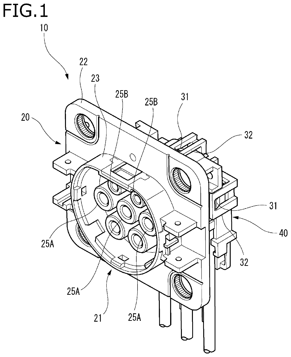
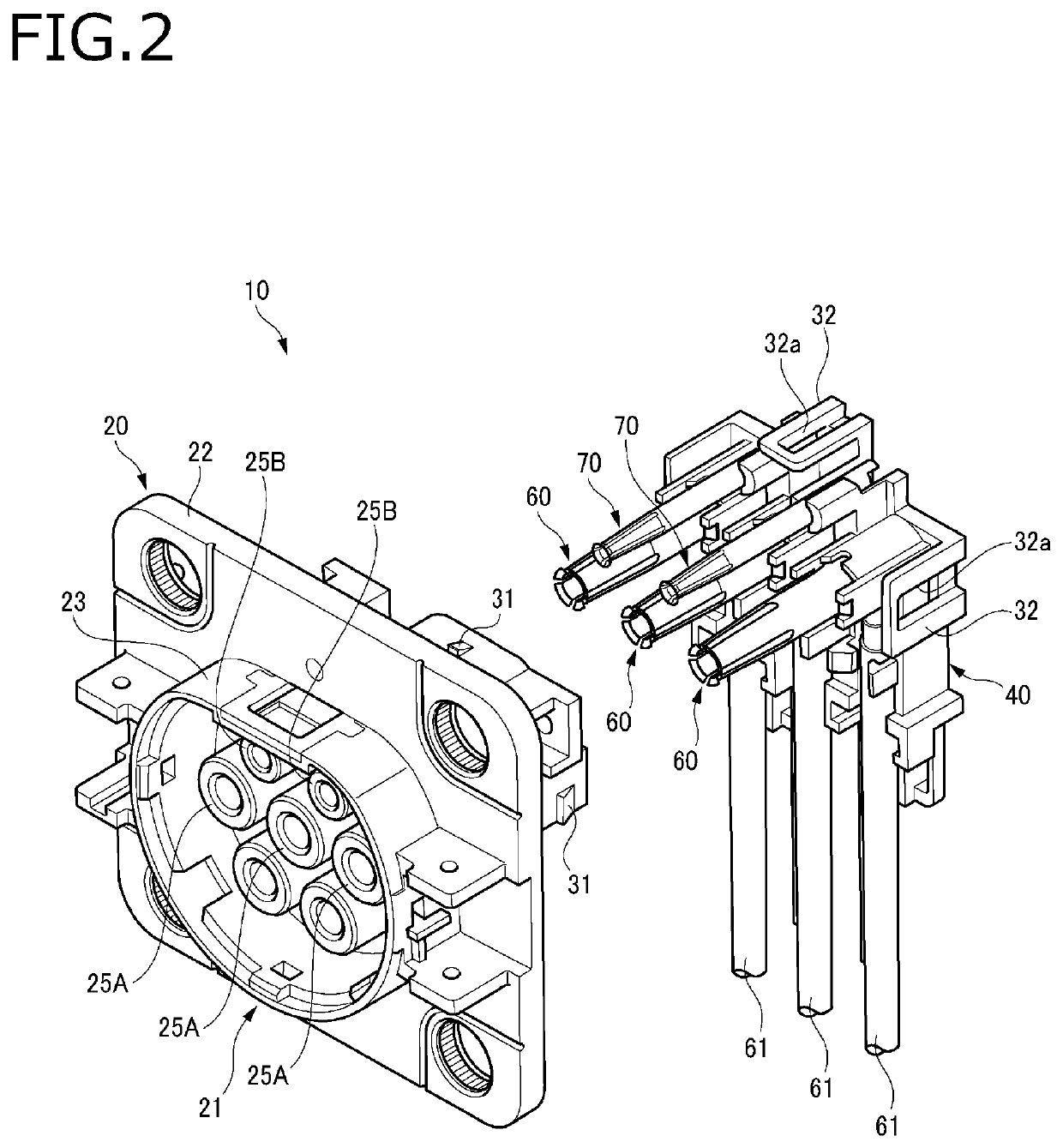
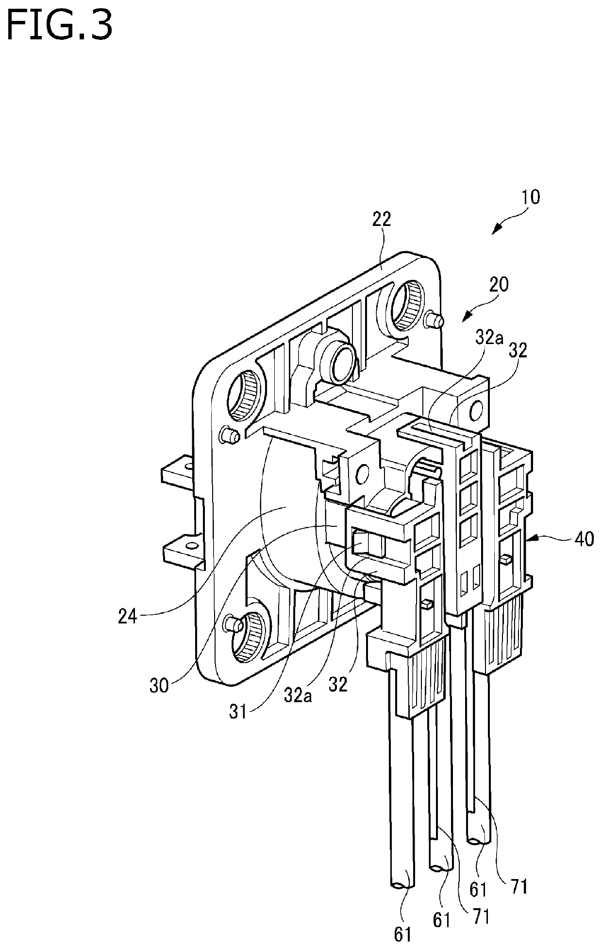
[0044]FIG. 1 is a perspective view of a connector when viewed from a front side according to an embodiment. FIG. 2 is a perspective view of a housing and a rear holder when viewed from a front side. FIG. 3 is a perspective view of the connector when viewed from a rear side according to the embodiment. FIG. 4 is a perspective view of the housing and the rear holder when viewed from a rear side.

[0045]As illustrated in FIG. 1 to FIG. 4, a connector 10 according to the embodiment includes a housing 20, a rear holder 40, first terminals 60 and second terminals 70. The first terminals 60 are power supply terminals and are connected to end portions of power supply wires 61 respectively, and the second terminals 70 are signal terminals and are connected to end portions of signal wires 71 respectively.

[0046]The connector 10 according to the embodiment, for example, is mounted on a vehic...


PUM


Abstract

A connector includes a terminal configured to be connected to a mating terminal, and having an electric wire led out in a direction orthogonal to a connection direction in which the terminal is connected to the mating terminal, a housing having a cavity part configured to accommodate the terminal, and a rear holder having a terminal holding part configured to hold the terminal. The terminal is accommodated in the cavity part when the rear holder is assembled to the housing. The rear holder includes a locking mechanism that locks the terminal or the electric wire and that maintains a state of the terminal being held in the terminal holding part.

Description

CROSS REFERENCE TO RELATED APPLICATIONS[0001]This application is based on Japanese Patent Application (No. 2018-060354) filed on Mar. 27, 2018, the contents of which are incorporated herein by reference.BACKGROUND OF THE INVENTION1. Field of the Invention[0002]The present invention relates to a connector.2. Description of the Related Art[0003]There has been known a connector including a holder (rear holder) that is fitted into a housing and supports an electric wire connected to a terminal accommodated in the housing (see JP-A-2015-8099). The holder includes a first holder having a locking part, and a second holder with which the first holder clamps the electric wire by having a part to be locked at the locking part.[0004]Further, there has been known a plug insert, including: a holding block member that has an opening part opening to an outer side of a circumference; a contact member that is inserted into the opening part of the holding block member from the outer side of the circu...

Claims


Application Information

Patent Timeline
Patent Type & Authority Patents(United States)
IPC IPC(8): H01R13/436H01R13/506H01R13/58
CPCH01R13/582H01R13/506H01R13/4367H01R2201/26H01R13/436H01R13/502H01R13/56H01R13/58
Inventor YANAGIBASHI, KOUJIIKEYA, NAOTOTSUSHIMA, YOSHITAKAOKAMOTO, MASAYA
Owner YAZAKI CORP
Why Eureka
Try Eureka