Wire harness

a wire harness and wire technology, applied in the field of wire harnesses, can solve the problems of low degree of wiring freedom, high manufacturing cost of wire harnesses, and poor assembly workability of outer cover materials, and achieve the effect of reducing the length of the wire and good assembly workability

Inactive Publication Date: 2017-11-16
SUMITOMO WIRING SYST LTD
View PDF6 Cites 21 Cited by
  • Summary
  • Abstract
  • Description
  • Claims
  • Application Information

AI Technical Summary

Benefits of technology

[0019]According to the present invention, it is possible to provide a low-cost wire harness having an outer cover form having good assembly workability and installation workability for installing in vehicles and the like after coverage, and enables reduction of wire length.

Problems solved by technology

However, with the conventional wire harnesses described above, while it was possible for the outer cover materials to have multiple functions, the outer cover materials did not have good assembly workability or installation workability for installing a covered wire harness in vehicles and the like.
In addition, for each routing pattern, which differs depending upon the specifications of the wire harness, a dedicated assembly drawing board with jigs was used in which the corresponding wiring pattern was drawn on a plate surface thereof; thus, manufacturing cost of a wire harness was high due to reasons such as low recyclability of the assembly drawing board and the like.
Furthermore, since the outer cover materials were in a tube-shaped outer covering (cover) form, the outer covering form did not have a high degree of wiring freedom such that it might contribute to optimization of routing patterns of the wire harness or reduction of wire length.

Method used


Image

  • Wire harness
  • Wire harness
  • Wire harness

Examples


embodiment

[0029](Embodiment)

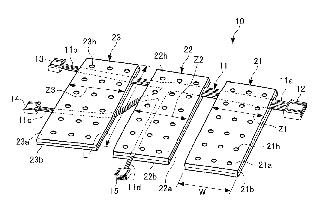
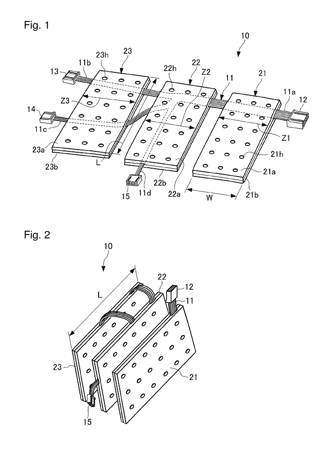
[0030]FIGS. 1 and 2 illustrate a wire harness according to one embodiment of the present invention.

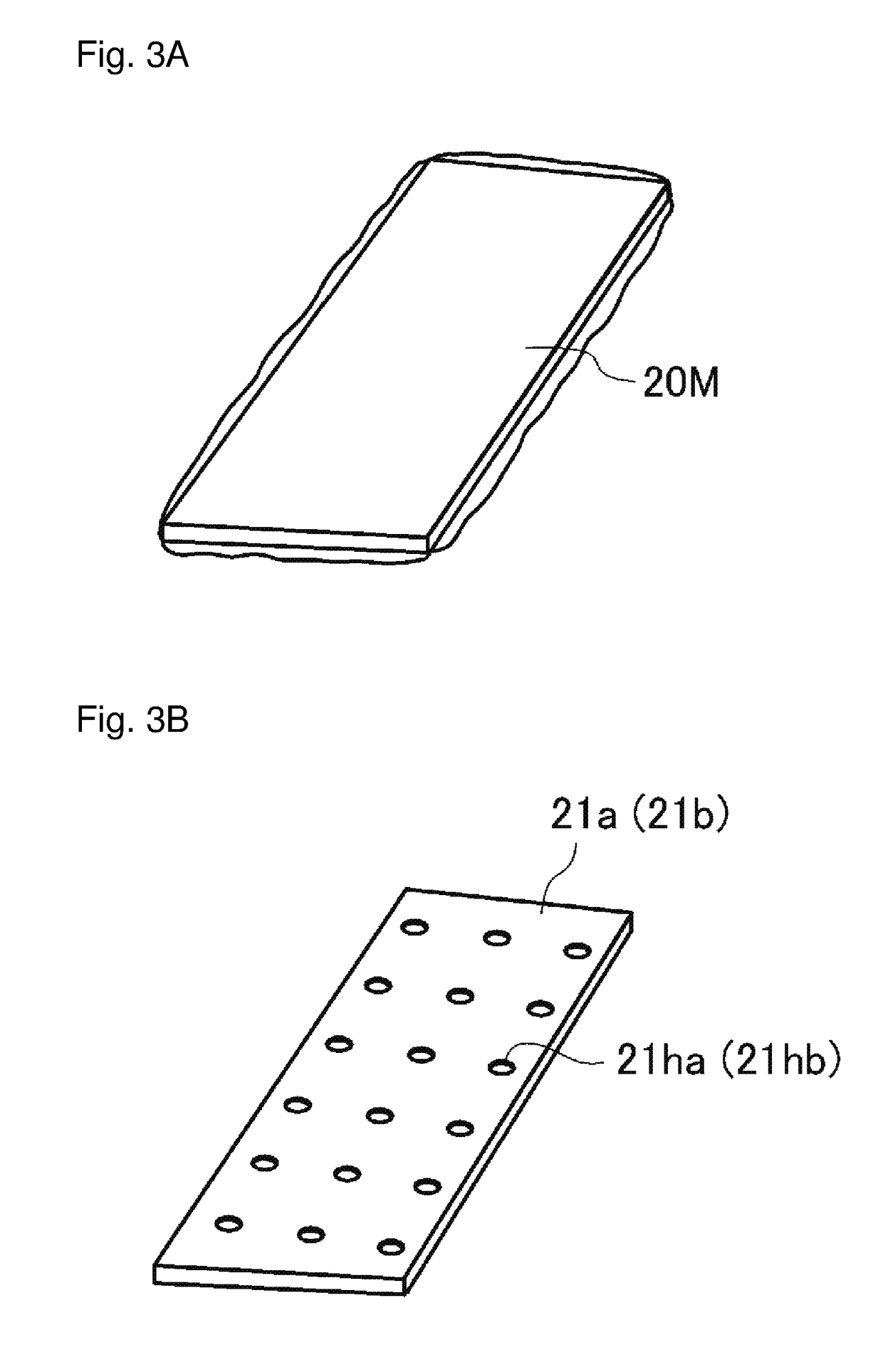
[0031]As illustrated in FIGS. 1 and 2, a wire harness 10 according to the present embodiment is a wire harness to be mounted on a floor surface side of a vehicle cabin of an automobile and is equipped with a group of wires in a bundled form configured by a plurality of electric wires, i.e., a wire bundle 11, a plurality of connectors 12, 13, 14 and 15 attached to the wire bundle 11, and a plurality of outer cover materials 21, 22 and 23 respectively covering, so as to protect the wire bundle 11, a plurality of outer coverage zones Z1, Z2 and Z3 arranged in a lengthwise direction along a routing path of the wire bundle 11.

[0032]Although not shown in detail in the drawings, the wire bundle 11 is configured by a plurality of electric wires including, for example, any of a power supply line, a signal line or a ground line or the like to an electric acuator or sensor or ot...


PUM

PropertyMeasurementUnit
widthaaaaaaaaaa
lengthaaaaaaaaaa
thicknessaaaaaaaaaa

Abstract

A wire harness includes a plurality of outer cover materials covering a plurality of outer coverage zones spaced in a lengthwise direction of a main line portion of a wire bundle, the plurality of outer cover materials being formed into a plate shape from their respective nonwoven material and being a plurality of plate-shaped bodies having a plate width in the lengthwise direction of the main line portion and a plate length greater than the plate width in a radial direction of the main line portion.

Description

FIELD OF THE INVENTION[0001]The present invention relates to a wire harness, and in particular a wire harness equipped with an outer cover material formed from a lightweight and flexible material such as a nonwoven fabric and the like.BACKGROUND OF THE INVENTION[0002]In wire harnesses mounted in vehicles such as automobiles and the like, outer cover materials are often attached to specific zones in a lengthwise direction of a group of wires for the purpose of wire protection and the like. Conventionally, outer coverage materials formed as porous fiber aggregates from nonwoven materials are known to be used to reduce product variation in an outer shape and to enhance protective functions and sound insulation.[0003]In this type of wire harness, an outer cover material is known, for example, in which an easily-bendable straight line portion is provided in a hot-pressed and plate-shaped nonwoven member, and the plate-shaped nonwoven member is folded or bent so as to cover electric wires...

Claims


Application Information

Patent Timeline
Patent Type & Authority Applications(United States)
IPC IPC(8): B60R16/02H01B7/08
CPCB60R16/0215H01B7/0823H01B13/01254
Inventor NAKAJIMA, HIROMICHI
Owner SUMITOMO WIRING SYST LTD
Why Eureka
Try Eureka