Head rest apparatus
- Summary
- Abstract
- Description
- Claims
- Application Information
AI Technical Summary
Benefits of technology
Problems solved by technology
Method used
Image
Examples
embodiment 1
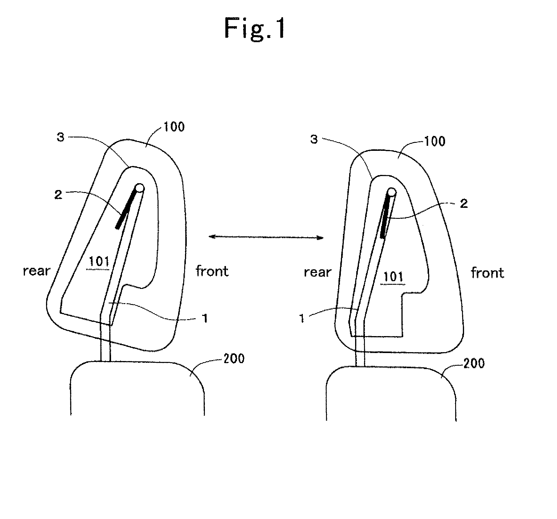
[0048]FIG. 1 is an explanatory view explaining the operation of the head rest apparatus of an embodiment. The head rest apparatus includes a metal stay 1, a metal plate 2 and a core member 3 housed in a head rest main body 100. The metal stay 1 is inserted into a seat back 200 and secured thereto. The metal plate 2 is rotatably supported on the horizontal rod of the metal stay 1 with a frictional resistance and fixed to the core member 3. A space 101 is provided within the core member 3 for allowing the movement of the leg portions of the metal stay 1 therein.
[0049]Accordingly, according to this head rest apparatus, by swinging or rotating the core member 3 and the metal plate 2 through the head rest main body 100, the position of the head rest in a front / rear direction can be adjusted as viewed in FIG. 1.
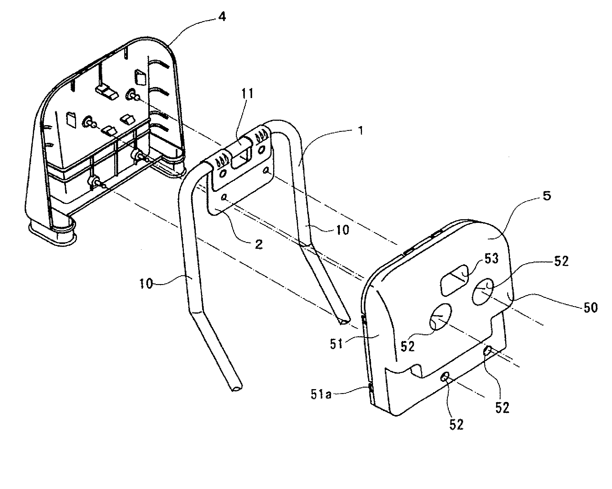
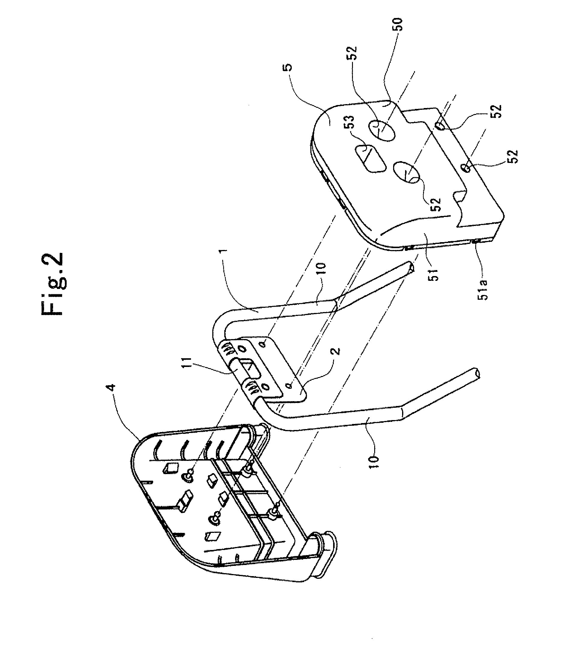
[0050]As shown in FIG. 2, the metal stay 1 has a reverse U-shape formed by a pair of leg portions 10 extending in approximately parallel with each other having a space therebetween...
embodiment 2
[0062]FIG. 9 shows a cross sectional view of the main part of the head rest apparatus according to this embodiment. The head rest apparatus of this embodiment is structured similar to that of the previous embodiment excepting that the upper two second connecting pins 52 among the four second connecting pins 52 of the second divided body 5 are separated from the front side surface of the flat plate portion 21. In this structure, the flat plate portion 21 is also tightly fixed to the first divided body 4 and the stress applied from the flat plate portion 21 upon rotation of the head rest main body 100 acts only on the first divided body 4 and the stress is absorbed within the first divided body 4 not to loosen the connection of the first divided body with the second divided body 5.
embodiment 3
[0063]FIG. 10 shows a cross sectional view of the main part of the head rest apparatus according to this embodiment. The head rest apparatus of this embodiment is structured similar to the first embodiment, excepting that instead of providing the second holding pawls 44, a projection 48 having a tapered portion 48a is provided. In this structure, the flat plate portion 21 is in contact with the pair of holding pawls 43 between the front surface of rib 47 and the stepped portion 45a of the first connecting pin 45 and is tightly fixed with three supporting points, and therefore, the stress applied from the flat plate portion 21 upon rotation of the head rest main body 100 acts only on the first divided body 4 and the stress is absorbed within the first divided body 4 to prevent generation of abnormal noise and rattling in operation.
[0064]It is noted that the head rest apparatus structured by combining the head rest apparatus according to the second embodiment with the head rest appara...
PUM
 Abstract
Description
Claims
Application Information
 - R&D
- Intellectual Property
- Life Sciences
- Materials
- Tech Scout
- Unparalleled Data Quality
- Higher Quality Content
- 60% Fewer Hallucinations
Browse by: Latest US Patents, China's latest patents, Technical Efficacy Thesaurus, Application Domain, Technology Topic, Popular Technical Reports.
© 2025 PatSnap. All rights reserved.Legal|Privacy policy|Modern Slavery Act Transparency Statement|Sitemap|About US| Contact US: help@patsnap.com


