
Cooking apparatus

Inactive Publication Date: 2009-12-31
SAMSUNG ELECTRONICS CO LTD
View PDF17 Cites 20 Cited by
  • Summary
  • Abstract
  • Description
  • Claims
  • Application Information

AI Technical Summary

Benefits of technology

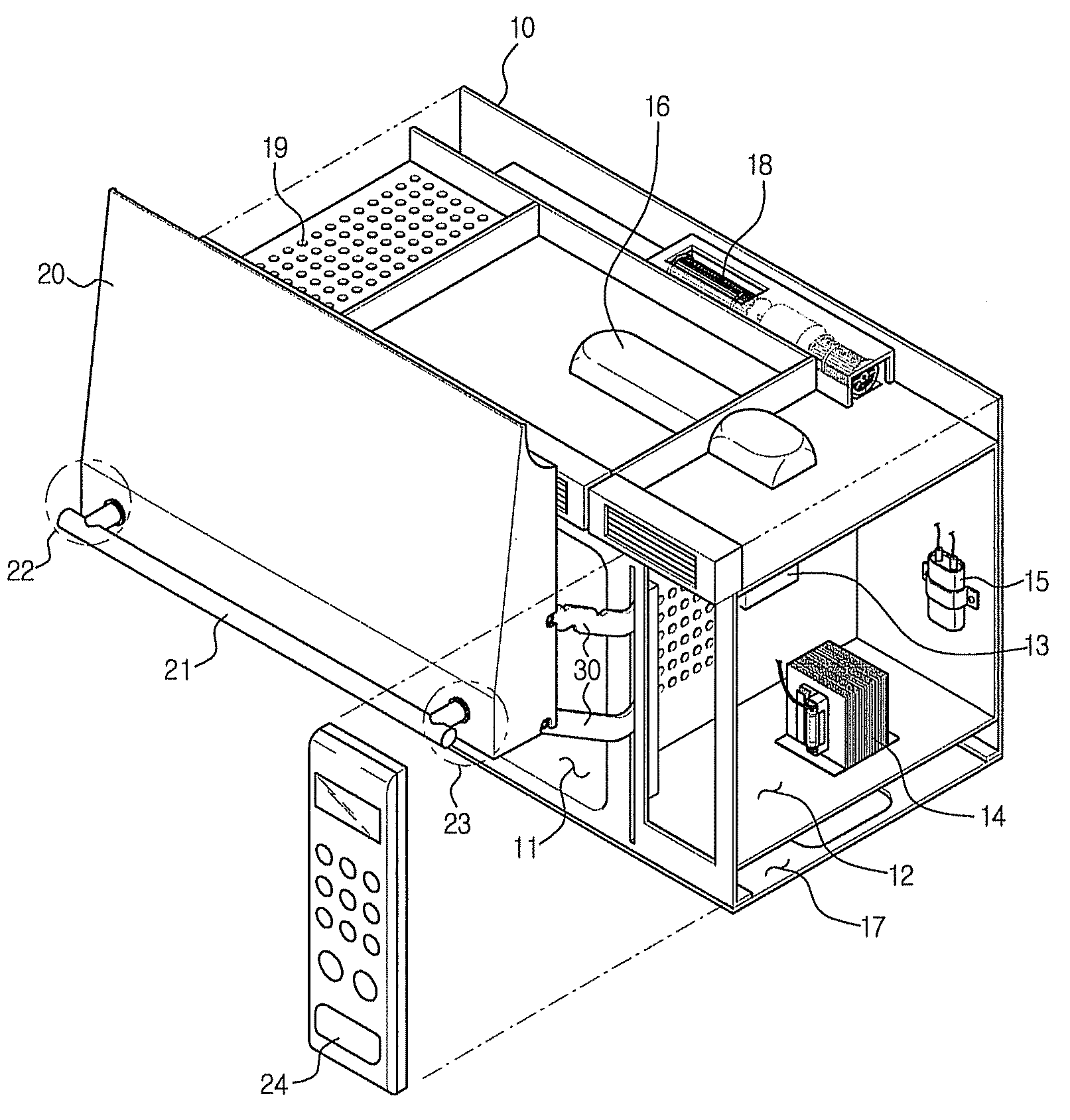
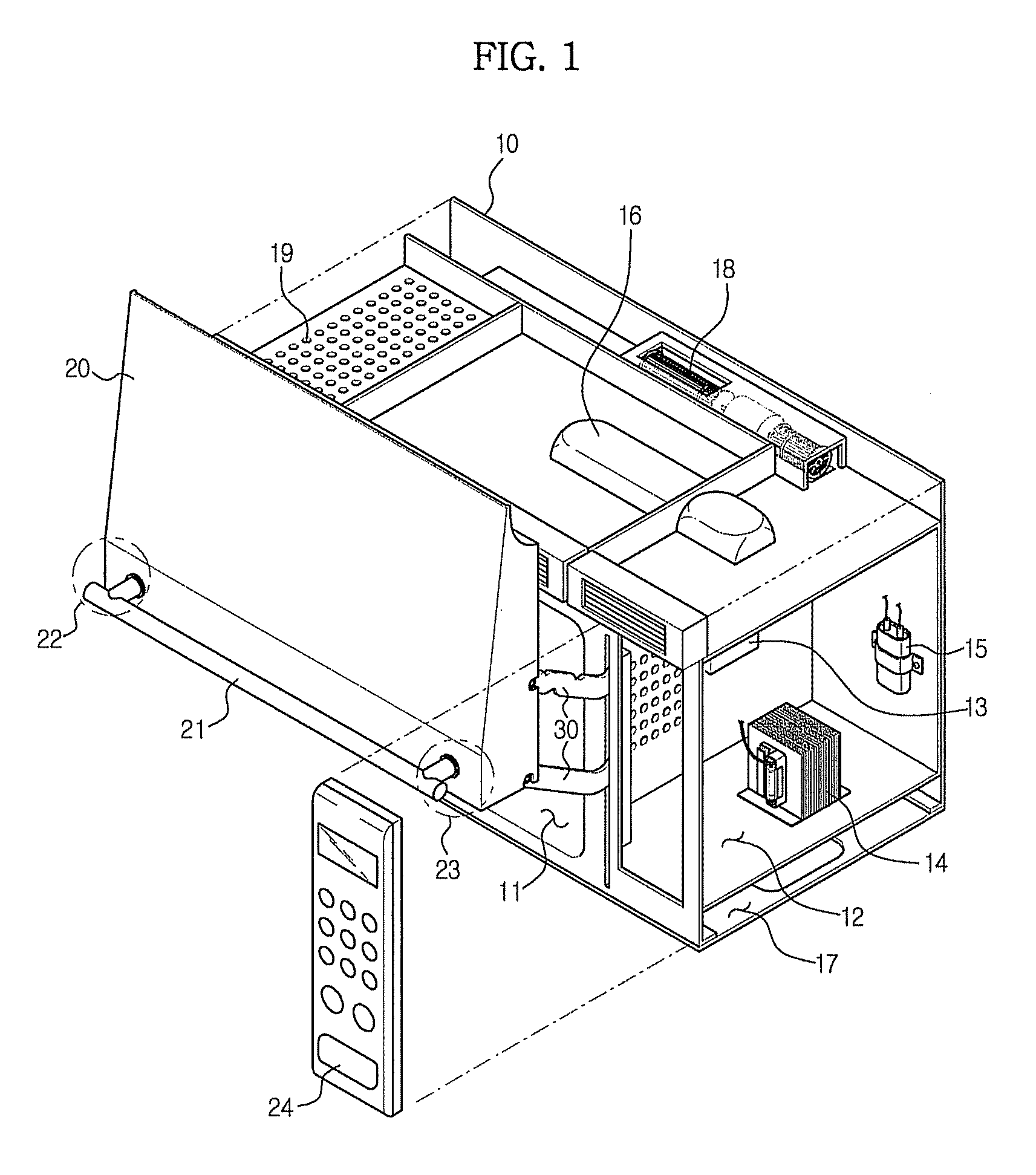
[0011]Therefore, it is an aspect of the invention to provide a microwave oven having a door coupling structure, by which rattling of a door is prevented and a door can be securely opened or closed.
[0012]It is another aspect of the invention to provide a microwave oven with an enhanced door sealing structure so as to prevent leakage of microwaves while a door is closed.
[0013]It is a further aspect of the invention to provide a microwave oven equipped with a device enabling a user to easily open a door.

Problems solved by technology

Because a conventional microwave oven has a door coupling structure such that a side portion of a door is hingedly coupled to a main body, when the door is in an opened state, the door may make interference with racks installed around the microwave oven.
Further, because the installation position of the microwave oven is generally set to a user's height, preferably, a user's eye level, there is a risk that a user gets hurt when she / he cooks food using an oven range while the door of the microwave oven is opened.
EP 0 754 920 B1 has a problem such that a door cannot be securely opened or closed.
Therefore, when a user opens or closes the door, the door rattles.
This may cause a problem that microwaves leak or a problem that a microwave switch cuts off power supply and thus the operation of the microwave oven is abnormally terminated.

Method used


Image

  • Cooking apparatus
  • Cooking apparatus
  • Cooking apparatus

Examples


second embodiment

[0089]FIG. 12 is a sectional view showing the second pressing device to rotate the cam portion.

[0090]Similar to the second pressing device 70 shown in FIG. 9, a second pressing device 70 shown in FIG. 12 is mounted to the cam portion 50. The second pressing device 70 of this embodiment is positioned above the pin (P) to rotate the cam portion 50 in a clockwise direction.

[0091]While the second pressing device 70 shown in FIG. 9 is constituted such that the second elastic member 72 is connected to the connecting pin 71 provided at the cam portion 50, the second pressing device 70 shown in FIG. 12 is constituted such that a connecting hole 74 is formed at the cam portion 50, an auxiliary connecting member 75 is connected to the connecting hole 74, and a second elastic member 76 pulls the auxiliary connecting member 75.

third embodiment

[0092]FIG. 13 is a sectional view showing the second pressing device to rotate the cam portion.

[0093]A second pressing device 70 shown in FIG. 13 is mounted to the cam portion 50, at a position below the pin (P), to rotate the cam portion 50 in a clockwise direction. Describing in detail, a connecting hole 74 is formed at the cam portion 50, and an auxiliary connecting member 75 is connected to the connecting hole 74. A second elastic member 76 is connected to the fixing bracket 40 so as to move the auxiliary connecting member 75 to the left. When the auxiliary connecting member 75 is moved to the left by the second elastic member 76, the auxiliary connecting member 75 pushes the cam portion 50 down so that the cam portion 50 is rotated in a clockwise direction.

fourth embodiment

[0094]FIG. 14 is a sectional view showing the second pressing device to rotate the cam portion.

[0095]Similar to the second pressing device 70 shown in FIG. 13, a second pressing device 70 shown in FIG. 14 is mounted to the cam portion 50, at a position below the pin (P). Also similar to the second pressing device 70 shown in FIG. 13, the second pressing device 70 shown in FIG. 14 is constituted such that a connecting hole 74 is formed at the cam portion 50, and an auxiliary connecting member 75 is connected to the connecting hole 74. However, different from the second pressing device 70 shown in FIG. 13, in which the second elastic member 76 is connected to the fixing bracket 40, the second pressing device 70 shown in FIG. 14 is constituted such that a second elastic member 76 is provided to be inserted into a cylinder 77. As shown in FIG. 14, when the second elastic member 76 moves the auxiliary connecting member 75 to the left, the auxiliary connecting member 75 pushes the cam por...


PUM


Abstract

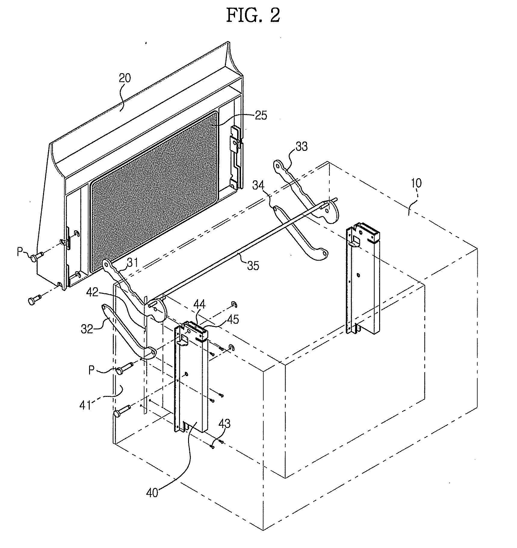
An opening / closing structure of a door of a microwave oven is disclosed. The microwave oven includes a main body having a cooking chamber, a door link-coupled to the main body to open or close the cooking chamber, at least one link member including a cam portion hingedly coupled to the main body so as to be rotated when the door is opened or closed, and a link control device to press the cam portion to control rotation of the link member. Accordingly, the door can be securely opened or closed without rattling.

Description

CROSS-REFERENCE TO RELATED APPLICATION[0001]This application claims the benefit of Korean Patent Application No. 2008-0060189, filed on Jun. 25, 2008 in the Korean Intellectual Property Office, the disclosure of which is incorporated herein by reference.BACKGROUND OF THE INVENTION[0002]1. Field of the Invention[0003]The present invention relates to a microwave oven, and more particularly, to a microwave oven equipped with a door which is opened or closed in an up / down direction by means of links.[0004]2. Description of the Related Art[0005]Generally, a microwave oven is an appliance for heating or cooking food using frictional heat caused by translational motion of water molecules contained in food by irradiating microwaves generated from a magnetron to food.[0006]Recently, in order to efficiently utilize a kitchen space, in many cases, a microwave oven is used together with an oven range rather than used independently. In other words, a microwave oven with a hood function is instal...

Claims


Application Information

Patent Timeline
IPC IPC(8): H05B6/68
CPCH05B6/6414H05B6/76F24C15/023F24C7/082
Inventor JEONG, SANG JIN
Owner SAMSUNG ELECTRONICS CO LTD
Learn More