Power transmitting toothed belt and power transmitting device

Inactive Publication Date: 2012-03-08
TSUBAKIMOTO CHAIN CO
View PDF11 Cites 5 Cited by
  • Summary
  • Abstract
  • Description
  • Claims
  • Application Information

AI Technical Summary

Benefits of technology

[0007]Accordingly, the invention aims at solving the aforementioned prior art problems by providing a power transmitting toothed belt and a power transmitting device capable of improving positioning accuracy between a power transmitting toothed belt and a pulley, improving durability of the belt and suppressing contact noise.
[0011]Accordingly, the power transmitting toothed belt of the invention prevents the rattling that would be otherwise generated when the belt teeth contact the straight pulley teeth. It further prevents backlash and bias of the belt in the direction of the width of the pulley. The belt of the invention also improves positioning accuracy between the belt teeth and the straight pulley teeth by preventing elastic elongation of the rubber back layer and the toothed layer. It further relieves contact noise and improves durability of the pulley and the belt by reducing wear of the belt teeth and of the pulley teeth.
[0012]In a preferred embodiment, the twisting direction of each of the plurality of core wires is the same. Because the core wires are embedded into the rubber back layer in the circumferential direction and the twisting directions are the same, the invention prevents the load (thrust force) from being biased in direction of the width of the pulley. Positioning errors between the belt teeth and the pulley teeth are prevented and durability is increased due to reduced belt wear.
[0013]In another embodiment, the belt teeth are tapered. That is, the width of each tooth becomes narrower proceeding from the base of the tooth toward the top. A load acting on the belt, i.e., a thrust force, is released along the surface of the belt tooth. Bias in the direction of the width of the belt is prevented and positioning error is reduced.

Problems solved by technology

There are problems with the power transmitting devices of the prior art which have straight belt teeth.
Thus, the durability of the toothed belt 210 is low and it becomes difficult to suppress contact noise.
The belt is unable to sustain the load imparted by the pulley to the belt, causing elastic elongation of the belt along with positioning errors between the belt teeth and the pulley teeth.

Method used


Image

  • Power transmitting toothed belt and power transmitting device
  • Power transmitting toothed belt and power transmitting device
  • Power transmitting toothed belt and power transmitting device

Examples


Embodiment Construction

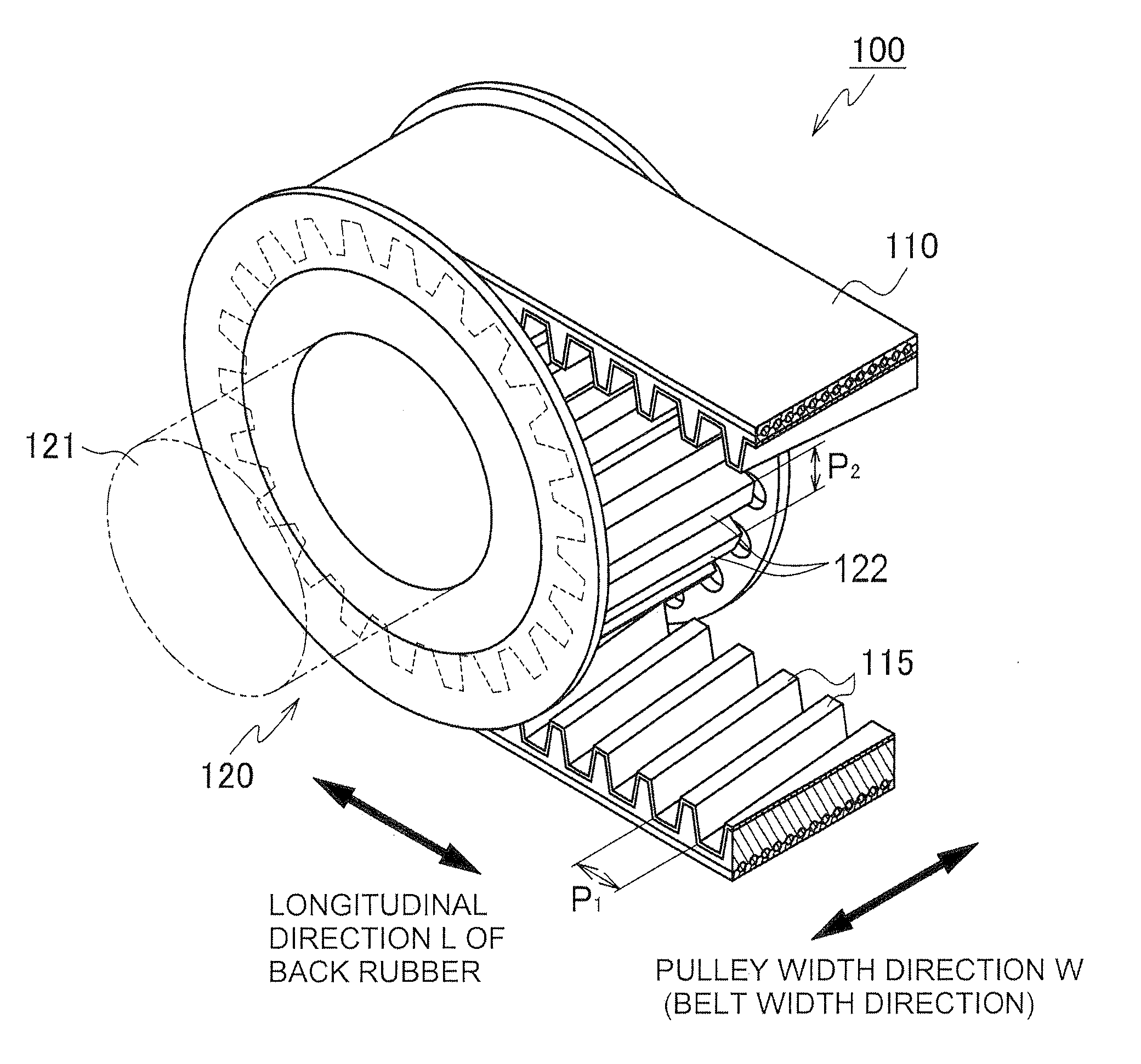
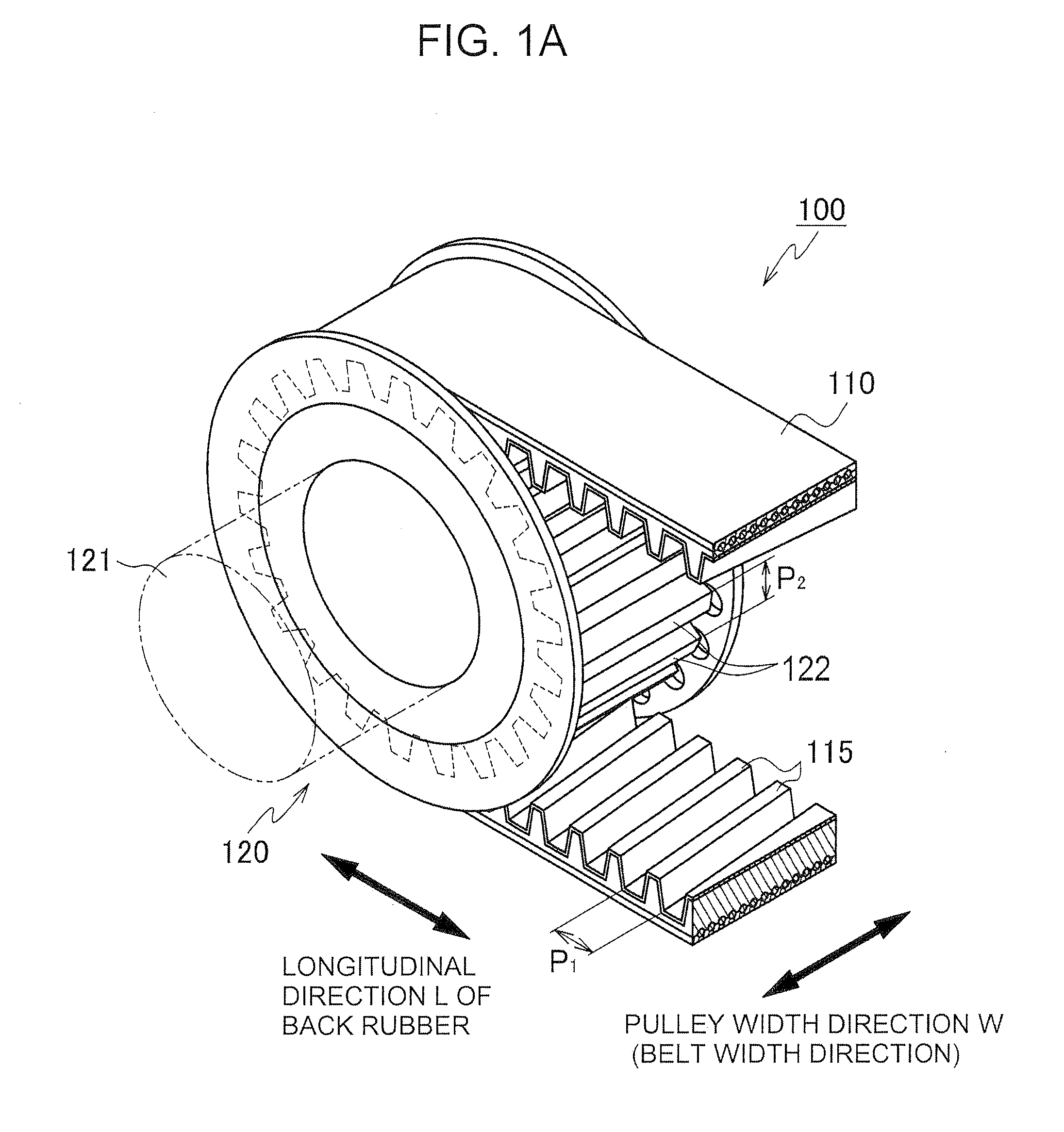
[0034]As shown in FIG. 1A, the power transmitting device 100 of the first embodiment of the invention has a pulley 120 that rotates on a shaft 121, and a toothed belt 110 that is wound around the pulley 120 to transmit power. The device 100 transmits power from the toothed belt 110 to the pulley 120 or from the pulley 120 to the toothed belt 110.

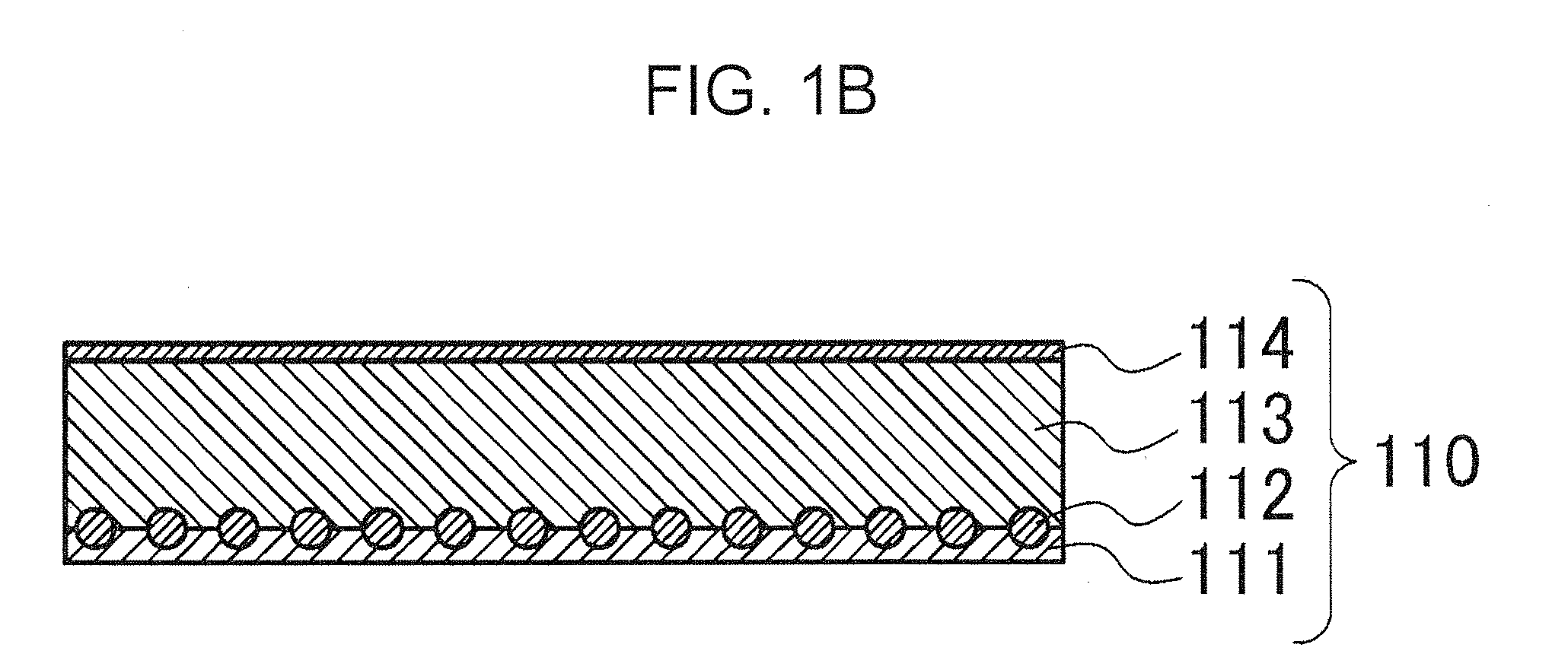
[0035]As shown in FIG. 1B, the toothed belt 110 of the power transmitting device 100 has a back layer 111 composed of rubber, a plurality of core wires 112 embedded into the back layer 111 and extending along longitudinal direction L (FIG. 1A) of the back layer 111, and a toothed rubber layer 113 forming a plurality of belt teeth 115 (FIG. 1A) on the plurality of core wires 112. A ground fabric layer 114 overlies the belt teeth. The device 100 transmits power between the toothed belt 110 and the pulley 120 by engagement of the belt teeth 115 with straight pulley teeth 122, which extend in the direction of the width of the pulley 120, i.e., p...


PUM

PropertyMeasurementUnit
Angleaaaaaaaaaa
Angleaaaaaaaaaa
Transmissionaaaaaaaaaa

Abstract

A power transmitting toothed belt having improved positioning accuracy between the toothed belt and a pulley, increased durability, and reduced contact noise, comprising a rubber back layer, a plurality of core wires and a rubber layer having a plurality of belt teeth, wherein the belt teeth are at oblique angle with respect to the direction of the width of the belt. The belt teeth intersect with straight pulley teeth having a pitch equal to the pitch of the belt teeth.

Description

CROSS REFERENCE TO RELATED APPLICATIONS)[0001]This application claims priority on the basis of Japanese Patent Application No. 2010-201195, filed on Sep. 8, 2010 in the Japan Patent Office. The disclosure of Japanese Patent Application No. 2010-201195 is herein incorporated by reference in its entirety.FIELD OF THE INVENTION[0002]The invention relates to a power transmitting toothed belt and a power transmitting device for use in industrial machines in general.BACKGROUND OF THE INVENTION[0003]A typical power transmitting toothed belt has straight belt teeth that extend parallel to the direction of the width of the belt. Alternatively, the belt may have v-shaped teeth as shown in Japanese Laid-open Patent Application 2000-346138. Other devices for transmitting power through a toothed belt include: an obliquely-toothed wheel that drives a toothed belt having oblique teeth as shown in Japanese Patent No. H03-3090; a transmission device that uses a toothed belt having curved belt teeth ...

Claims


Application Information

Patent Timeline
IPC IPC(8): F16H7/02F16G1/12F16G1/28
CPCF16H7/023F16G1/28F16G1/06
Inventor SHIMIZU, SHOICHIROSAKAMOTO, HIROSHIKANAMORI, MASARU
Owner TSUBAKIMOTO CHAIN CO
Why Eureka
Try Eureka