Slide device for vehicle seat

Active Publication Date: 2011-09-29
SUBARU CORP
View PDF6 Cites 13 Cited by
  • Summary
  • Abstract
  • Description
  • Claims
  • Application Information

AI Technical Summary

Benefits of technology

[0011]The present invention is made in view of the above, and it is an object of the present invention to provide a slide device for a vehicle seat that prevents the rattling of a seat body with a simple configuration while being capable of reliably moving a seat body in the front-rear direction upon a vehicle frontal crash.
[0013]According to the slide device for a vehicle seat of the present invention, rattling of the seat body is prevented by a simple configuration while the seat body can be reliably moved in the front-rear direction even upon a vehicle frontal crash.

Problems solved by technology

However, a space formed thereby between the lower rail and the rollers may cause the rollers to rattle.
However, if rollers are arranged in tandem at three or more positions on the upper rail, a smooth movement of the upper rail in the front-rear direction may be hindered when, for example, the lower rail is bent by an impact upon a vehicle frontal crash or the like.
In particular, in the case of a so-called three-row seating vehicle, which has three rows of seats in a vehicle compartment in the front-rear direction, if the front-rear movement of an seat body in the second row is hindered, it may be difficult for an occupant seated in the third row to escape quickly.
In order to address this problem while ensuring a smooth seat slide operation also upon a frontal crash, the lower rail may be composed of a highly rigid material for example, but the enhancement of the rigidity of the lower rail could cause an increase in weight, a steep rise in cost, or the like.

Method used


Image

  • Slide device for vehicle seat
  • Slide device for vehicle seat
  • Slide device for vehicle seat

Examples


Embodiment Construction

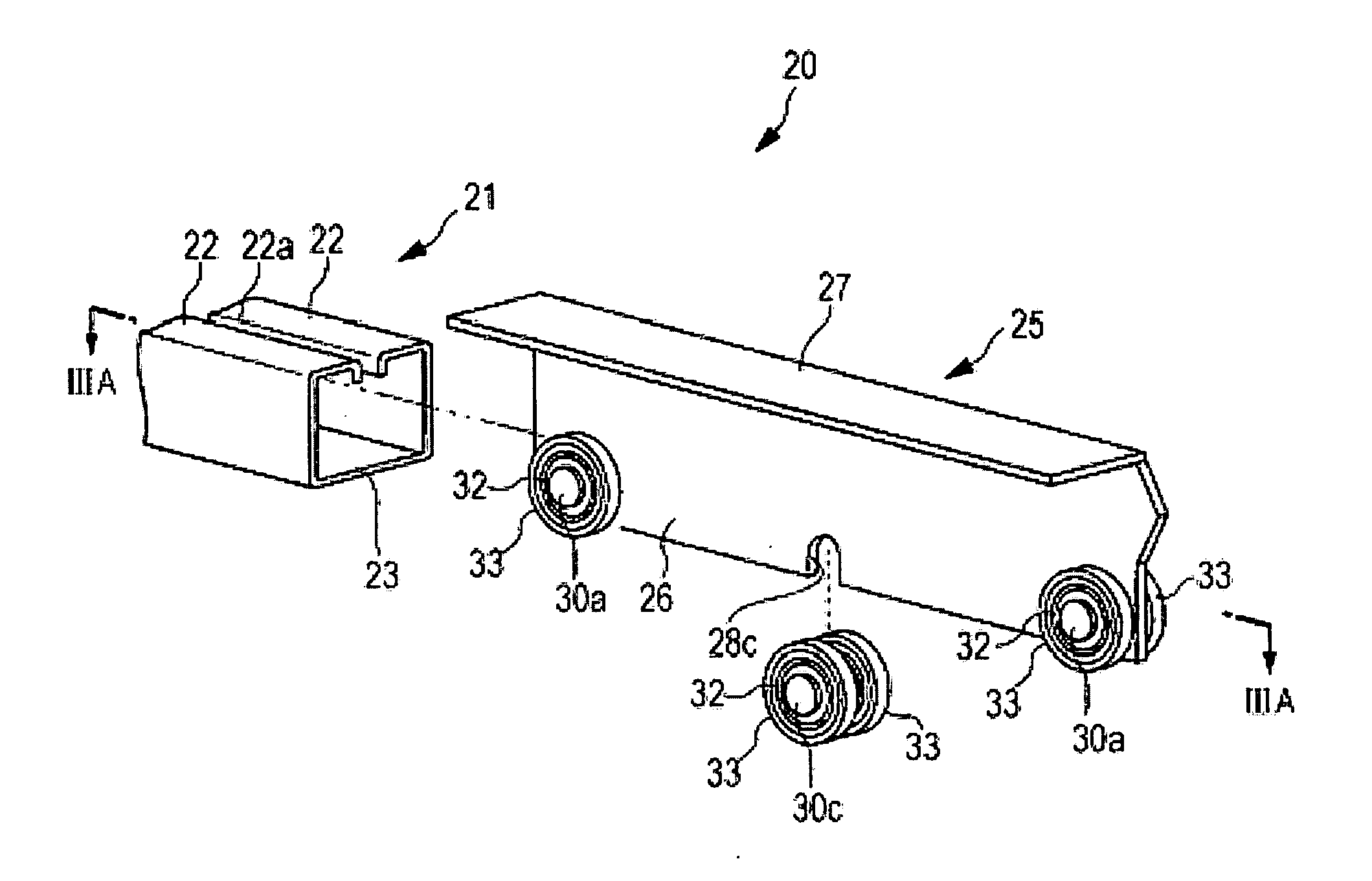
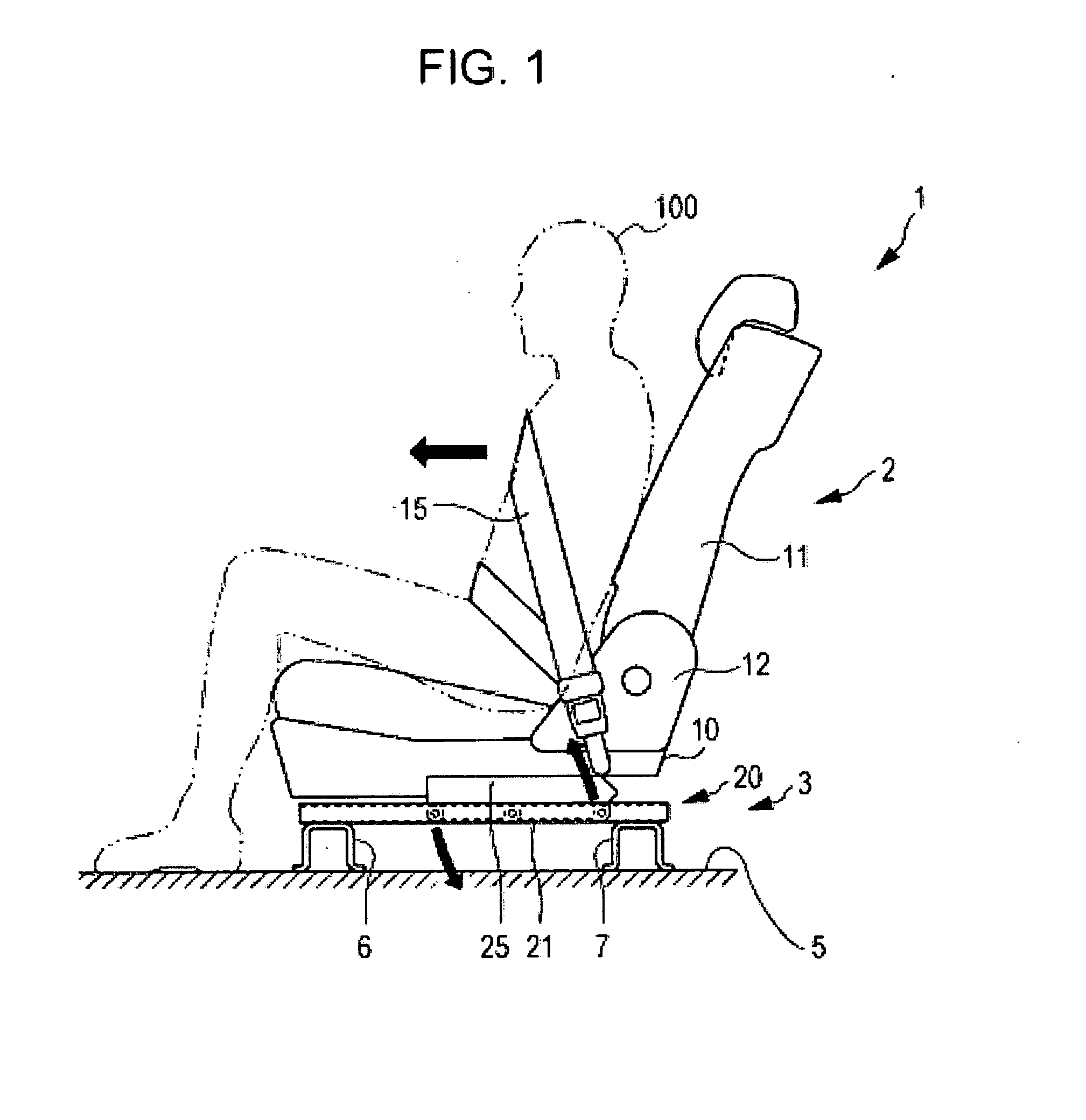
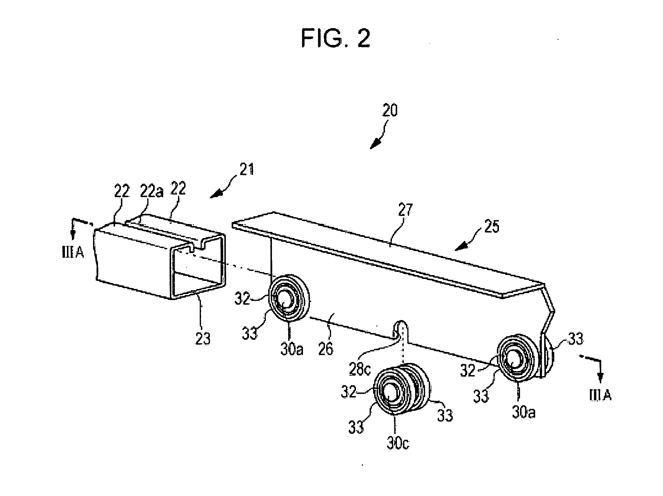
[0020]An embodiment of the present invention will hereunder be described with reference to the drawings. The drawings relate to one embodiment of the present invention. FIG. 1 is a schematic structural view of a vehicle seat. FIG. 2 is an exploded perspective view of a main part of a slide device. FIG. 3A is a sectional view of the slide device taken along the line IIIA-IIIA of FIG. 2. FIGS. 3B and 3C are enlarged sectional views of main parts. FIG. 4A is a sectional view of a main part taken along the line IVA-IVA of FIG. 3B. FIG. 4B is a sectional view of a main part taken along the line IVB-IVB of FIG. 3C. FIG. 5 is a side view of an upper rail. FIGS. 6A and 6B are explanatory views of an action of the upper rail when a lower rail is bent. FIG. 6C is an enlarged sectional view showing a main part of FIG. 6B.

[0021]A vehicle seat 1 shown in FIG. 1 is, for example, a seat that is disposed in the second row of a so-called three-row seating vehicle, which has three rows of seats in a ...


PUM


Abstract

A slide device for vehicle seat in which rollers are arranged at three positions on a lower rail including front and rear portions thereof. Among the rollers, the rollers located at the front and rear portions of the upper rail are pivotally supported by roller shafts and that are prohibited from moving on the upper rail, while the rollers located at the position other than the front and rear portions of the upper rail are pivotally supported by a roller shaft that is allowed to move downward on the upper rail.

Description

CROSS REFERENCES TO RELATED APPLICATIONS[0001]The present application claims priority from Japanese Patent Application No. 2010-072395 filed on Mar. 26, 2010, the entire contents of which are hereby incorporated by reference.BACKGROUND OF THE INVENTION[0002]1. Field of the Invention[0003]The present invention relates to a slide device for a vehicle seat that moves a seat body in the front-rear direction of a vehicle body by a relative movement of an upper rail to a lower rail.[0004]2. Description of the Related Art[0005]A typical slide device for a vehicle seat is mainly configured with a lower rail being fixedly installed on a floor of a vehicle body and extending in the front-rear direction of the vehicle body, and an upper rail being coupled to the lower rail so as to be relatively movable and supporting a seat body.[0006]In this type of slide device, the coupling of the upper rail to the lower rail is generally achieved by rollers that are respectively attached to front and rear...

Claims


Application Information

Patent Timeline
IPC IPC(8): B60N2/07
CPCB60N2/07
Inventor KITAMURA, ATSUOOFUJI, YUTAKA
Owner SUBARU CORP
Why Eureka
Try Eureka