Connector

Active Publication Date: 2019-03-14
SUMITOMO WIRING SYST LTD
View PDF80 Cites 0 Cited by
  • Summary
  • Abstract
  • Description
  • Claims
  • Application Information

AI Technical Summary

Benefits of technology

The patent text describes a front retainer and housing assembly that prevents rattling between the two components. The front retainer has a locking surface and a locking projection that lock into the locking surface. The locking surface is inclined with respect to the assembly direction of the front retainer, which prevents rattling due to dimensional tolerances and assembly tolerances. The front retainer can be moved between a partial locking position and a full locking position, and the locking projection bites into the locking surface at different positions to prevent rattling at both positions. The technical effect of this invention is to prevent rattling between the front retainer and the housing, ensuring reliable connection and stability during assembly.

Problems solved by technology

Thus, dimensional tolerances and assembly tolerances are unavoidable, and rattling may occur between the locking projection and the lock when the front retainer is assembled with the housing.

Method used


Image

  • Connector
  • Connector
  • Connector

Examples


Embodiment Construction

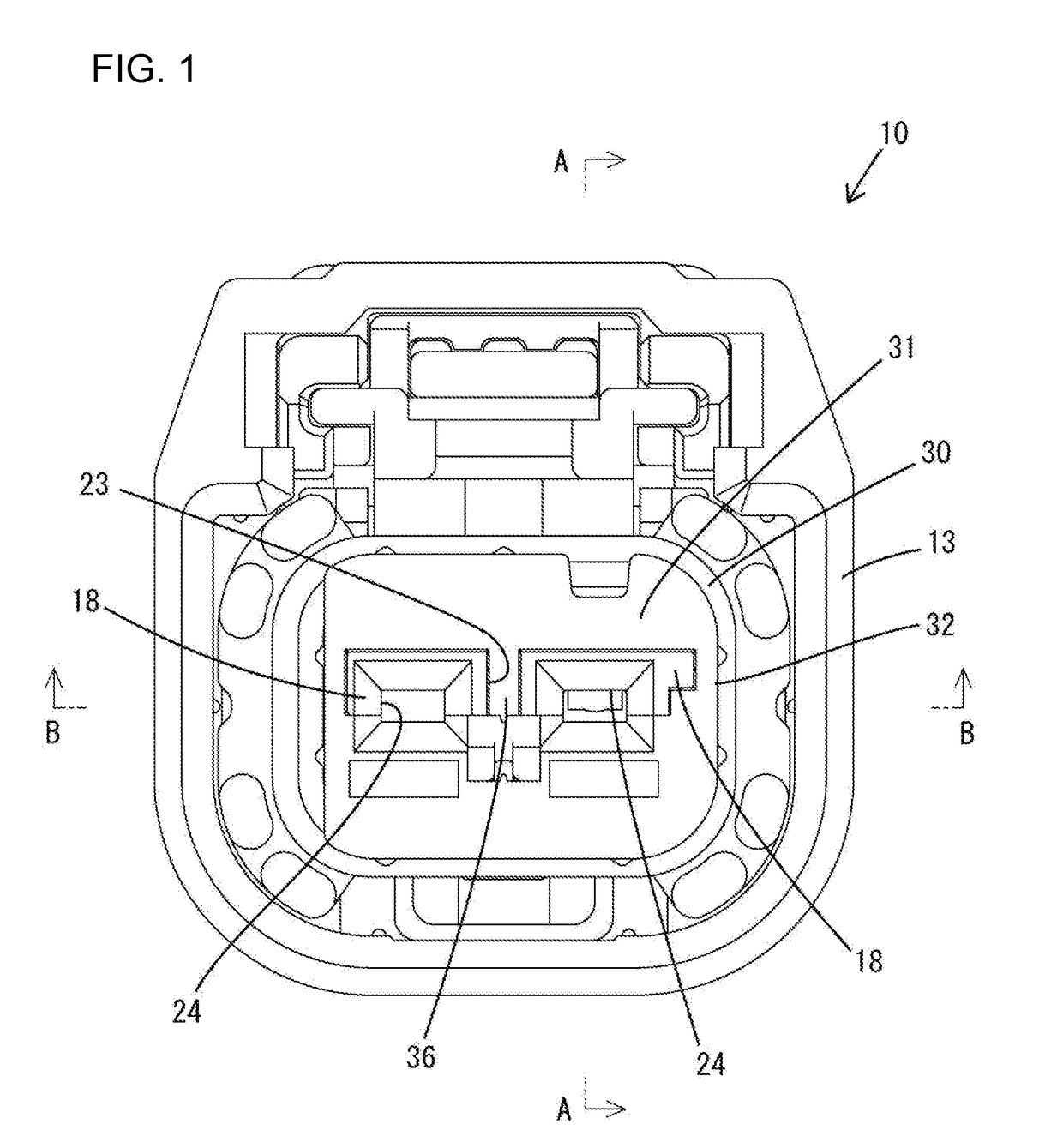
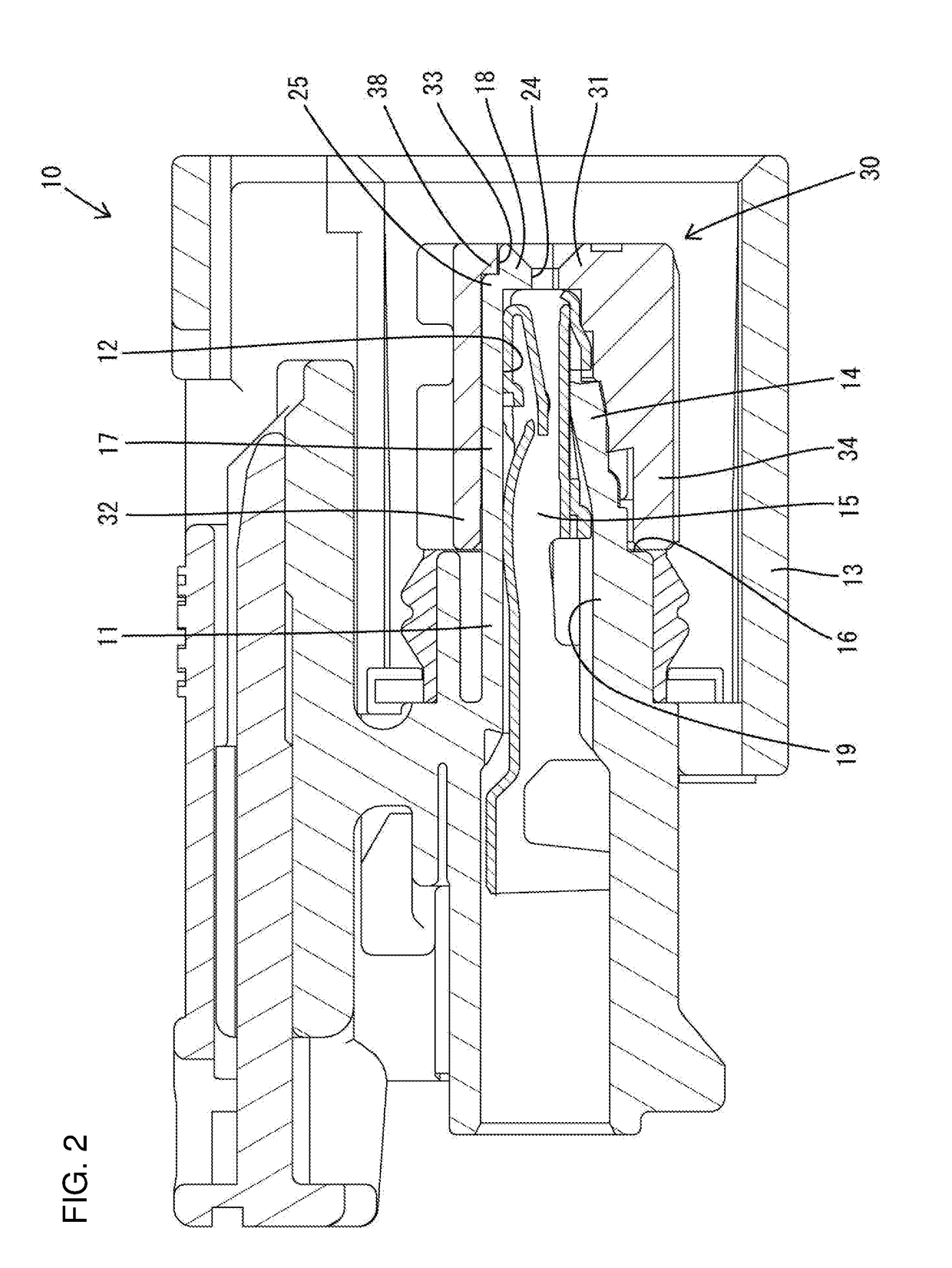
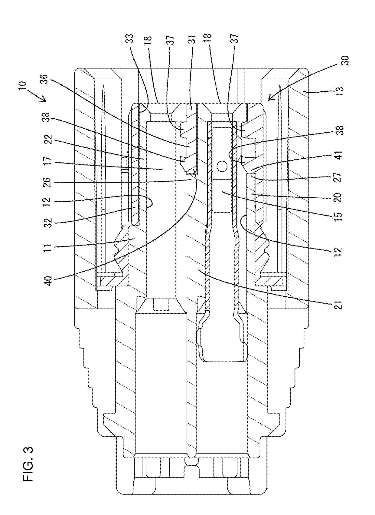
[0028]An embodiment of the invention is described with reference to FIGS. 1 to 15. Note that, in the following description, a right side in FIGS. 2, 3, 5 to 10 and 12 to 14 is defined as a front side concerning a front-rear direction. Upper and lower sides shown in FIGS. 1, 2, 4, 5, 7, 9, 11 and 12 are defined as upper and lower sides concerning a vertical direction. A lower side in FIGS. 3, 6, 8, 10 and 13 is a right side concerning a lateral direction.

[0029]

[0030]A connector of this embodiment includes a housing 10 made of synthetic resin, terminal fittings 15 made of metal and a front retainer 30 made of synthetic resin. The housing 10 is a single member made of polyamide resin (PA) and includes a terminal accommodating portion 11 having left and right terminal accommodation chambers 12 and a receptacle 13 surrounding the terminal accommodating portion 11. Each terminal accommodation chamber 12 has a forwardly cantilevered locking lance 14. The terminal fitting 15 is inserted int...


PUM


Abstract

A connector includes a housing (10) formed with a terminal accommodating portion (11), terminal fittings (15) to be inserted into the terminal accommodating portion (11) from behind, a front retainer (30) to be assembled with the housing (10) from front, and locking surfaces (29) formed in the terminal accommodating portion (11) and configured to hold the front retainer (30) and the housing (10) in an assembled state by having locking projections (37) of the front retainer (30) locked thereto from behind. The locking surfaces (29) are inclined with respect to an assembling direction of the front retainer 30 with the housing (10).

Description

BACKGROUNDField of the Invention[0001]The invention relates to a connector.Related Art[0002]Japanese Unexamined Patent Publication No. 2015-144103 discloses a connector including a housing formed with a terminal accommodating portion. A terminal fitting is inserted into the terminal accommodating portion from behind the housing. A front retainer is assembled with a front part of the housing from the front and is configured to detect an inserted state of the terminal fitting. The terminal accommodating portion includes a base extending along an inserting direction of the terminal fitting, a front wall projecting substantially at a right angle from a front end of the base, a tab insertion recess formed by recessing a projecting edge of the front wall and a lock projecting from a front part of a side edge of the base and linked to the front wall.[0003]The front retainer is formed with a butting portion that is in contact with the housing from the front when the front retainer is assemb...

Claims


Application Information

Patent Timeline
IPC IPC(8): H01R13/436H01R13/426H01R13/502H01R13/629H01R13/05
CPCH01R13/4365H01R13/426H01R13/502H01R13/629H01R13/055H01R13/42H01R13/4223H01R13/639
Inventor HASHIMOTO, NORIHITOYAMANAKA, WATARU
Owner SUMITOMO WIRING SYST LTD
Why Eureka
Try Eureka