

Rotating tool
- Summary
- Abstract
- Description
- Claims
- Application Information
AI Technical Summary
Benefits of technology
Problems solved by technology
Method used
Image

Examples
example 1
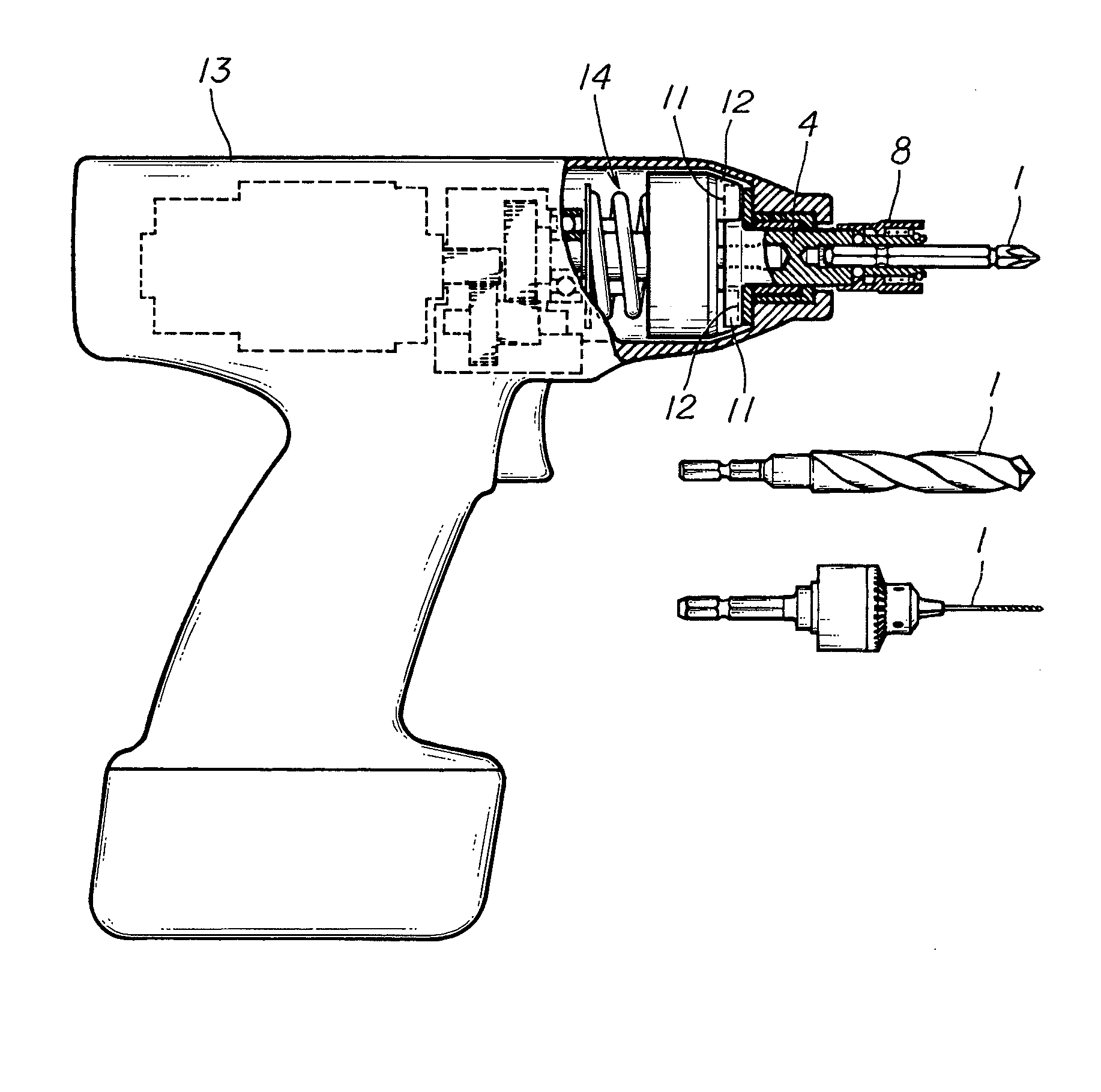
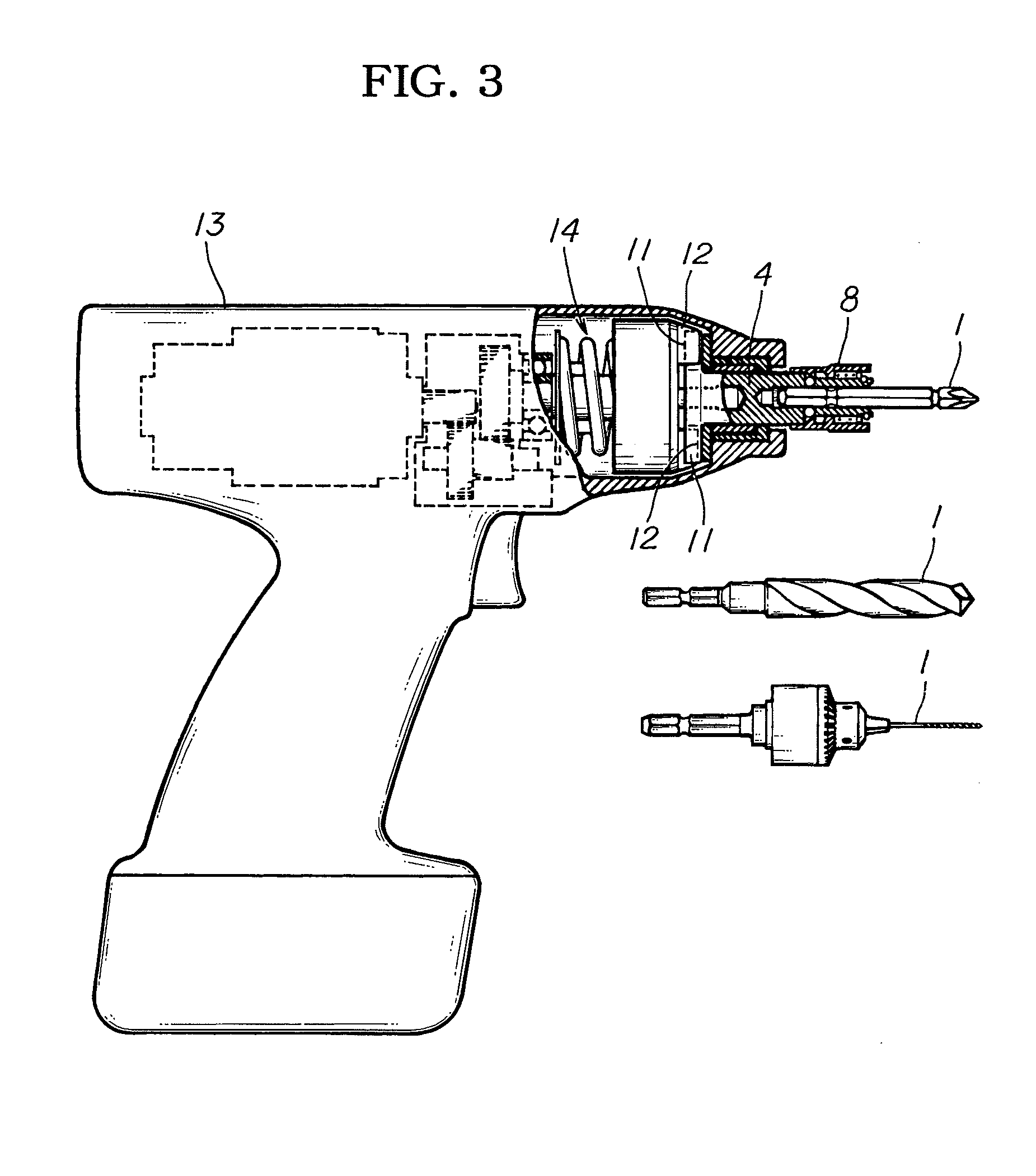
[0054]Example 1 of the present invention will be described based on FIGS. 3 through 7.
[0055]Example 1 is a rotating tool having a rotating main shaft 4 in which the rotating main shaft 4 is provided with a machine tool retaining hole 3 having a cross-sectional shape that substantially matches a base part 2 of a driver bit, drill bit, or other machine tool 1 having a polygonal cross-sectional shape that is inserted into the machine tool retaining hole 3, wherein the rotating tool rotates the machine tool 1 inserted in the machine tool retaining hole 3 by rotating the rotating main shaft 4 and performs work. The rotating tool is provided with a pushing mechanism for rotating the machine tool 1 in a prescribed direction in a state in which the machine tool 1 is inserted in the machine tool retaining hole 3, and twisting and pushing the machine tool 1 against an internal surface of the machine tool retaining hole 3.
[0056]As shown in FIG. 3, Example 1 is an example in which the present i...
example 2
[0083]Example 2 of the present invention will be described based on FIGS. 8 through 16.
[0084]Instead of the pushing mechanism of Example 1, a configuration is adopted in Example 2 in which a rotating body 10 in which an insertion passage hole 9 communicated with the machine tool retaining hole 3 is provided to the distal end part of a machine tool retaining hole 3 such as the one shown in FIGS. 8 and 9, and the rotating body 10 is provided with a rotational urging mechanism for rotating the insertion passage hole 9 and a machine tool 1 inserted in the machine tool retaining hole 3 in a prescribed direction.
[0085]The sliding tube 8 urged towards the proximal end is fitted to the distal end part of the machine tool retaining hole 3, and the rotational urging mechanism is provided between the machine tool retaining hole 3 and the sliding tube 8.
[0086]Specifically, as shown in FIG. 16, a pair of locking tabs 27, 28 for engaging with concave grooves 29 formed in the rotating main shaft 4...
example 3
[0094]Example 3 of the present invention will next be described based on FIGS. 17 through 23.
[0095]The rotational urging mechanism of Example 3 differs from the rotational urging mechanism of Example 2 in that an insertion passage hole 9 is not rotated by insertion of the machine tool 1.
[0096]Specifically, the sliding tube 8 urged towards the proximal end is fitted in the distal end part of the machine tool retaining hole 3, and an urging force does not act on the rotating body 10 when the sliding tube 8 is pulled towards the distal end against an urging force. The machine tool 1 is thus not rotationally urged in a prescribed direction. In a state in which the sliding tube 8 is moved back by the urging force towards the proximal end, the machine tool 1 is rotated in the prescribed direction, and the machine tool 1 is twisted and pushed against the internal surface of the machine tool retaining hole 3.
[0097]In the same manner as in Example 2, a pair of locking tabs 27, 28 for engagin...
PUM
| Property | Measurement | Unit |
|---|---|---|
| Force | aaaaa | aaaaa |
Abstract
Description
Claims
Application Information