Wheel Bearing Apparatus Incorporated with a Wheel Speed Detecting Apparatus

a technology of speed detection and bearings, which is applied in mechanical devices, instruments, transportation and packaging, etc., can solve the problems of inability to prevent ingress of foreign matter from outside the bearing apparatus, such as magnetic powder, into the space, and achieve the effects of improving assembly workability, simplifying the associated parts of the wheel rotation speed detecting sensor, and preventing damage and fallou

Inactive Publication Date: 2007-11-01
NTN CORP
View PDF12 Cites 22 Cited by
  • Summary
  • Abstract
  • Description
  • Claims
  • Application Information

AI Technical Summary

Benefits of technology

[0029] The encoder has an annular ring configuration with its characteristics alternately and equidistantly varying along its circumferential direction. The sensor holder is arranged radially inward from the outer circumferential surface of a knuckle fitting surface of the outer member. Terminals, for taking out output signal from the wheel rotation speed detecting sensor, extend radially outward and are connected to wire harnesses circumferentially arranged along the end surface of the outer member. Thus, it is possible to simplify the associated parts of the wheel rotation speed detecting sensor and to further improve the workability of assembly and to prevent the holding member and the wire harnesses from being projected radially outward and causing interference with the suspension apparatus of vehicle.
[0030] The wheel rotation speed detecting sensor is formed by a plurality of magnetic detecting elements. The wheel rotation speed detecting sensor and the leading-out portion for connecting the terminals and wire harnesses are integrally molded within the holding member by synthetic resin. This makes it possible to prevent damage and fall-out of the holding member which would be caused by flying gravel during running of the vehicle as well as the generation of corrosion of the terminals and the leading-out portion of the wire harnesses. Thus, this improves the reliability of the bearing apparatus.
[0031] A wheel bearing apparatus with an incorporated wheel speed detecting apparatus comprises an outer member with double row outer raceway surfaces formed on its inner circumferential surface. An inner member includes a wheel hub with an integrally formed wheel mounting flange at one end. A cylindrical portion axially extends from the wheel mounting flange. An inner ring is fit onto the cylindrical portion of the wheel hub. Double row inner raceway surfaces, opposite to the double row outer raceway surfaces, are formed on the outer circumferential surfaces of the wheel hub and inner ring, respectively. Double row rolling elements are arranged between the outer and inner raceway surfaces. An encoder is mounted on the outer circumferential surface of the inner ring. An annular sensor holder is arranged on the end of the outer member opposite to the encoder. A wheel rotation speed detecting sensor is integrally molded with the sensor holder and arranged opposite to the encoder, via a predetermined radial gap. The encoder has an annular ring configuration with its characteristics alternately and equidistantly varying along its circumferential direction. A seal is arranged at the inboard side of the encoder, via the sensor holder. The seal includes a first annular sealing plate and a second annular sealing plate mounted on the sensor holder and the inner ring, respectively, and opposite toward each other. Thus, it is possible to prevent ingress of foreign matter from outside of the bearing apparatus, such as magnetic powder, into a space between the magnetic encoder and the detecting portion of the wheel speed sensor even before the stem portion of the outer joint member is inserted into the wheel hub. The ingress is prevented even though it includes a course where the bearing apparatus is transferred to an assembly line of a manufacturer of automobiles. Also, ingress is prevented under severe circumstances in real running conditions of the vehicle. Thus, it is possible to remarkably improve the reliability of detection of the wheel rotation speed.
[0032] Another wheel bearing apparatus with an incorporated wheel speed detecting apparatus comprises an outer member with double row outer raceway surfaces formed on its inner circumferential surface. An inner member includes a wheel hub with an integrally formed wheel mounting flange at one end. A cylindrical portion axially extends from the wheel mounting flange. An inner ring is fit onto the cylindrical portion of the wheel hub. Double row inner raceway surfaces, opposite to the double row outer raceway surfaces, are formed on the outer circumferential surfaces of the wheel hub and inner ring, respectively. Double row rolling elements are arranged between the outer and inner raceway surfaces. An encoder is mounted on the outer circumferential surface of the inner ring. A sensor holder includes an annular fitting member. A holding member, in which a wheel rotation speed detecting sensor is embedded, is arranged opposite to the encoder via a predetermined radial gap. The encoder has an annular ring configuration with its characteristics alternately and equidistantly varying along its circumferential direction. The sensor holder is arranged radially inward from the outer circumferential surface of a knuckle fitting surface of the outer member. Terminals, for taking out output signals from the wheel rotation speed detecting sensor, extend radially outward and are connected to wire harnesses circumferentially arranged along the end surface of the outer member. Accordingly, it is possible to simplify the wheel rotation speed detecting sensor and its associated parts. Thus, this further improves the workability of assembly and prevents the holding member and the wire harnesses from projecting radially outward and causing interference with the suspension apparatus of vehicle.

Problems solved by technology

However, although the wheel bearing apparatus incorporated with a wheel speed detecting apparatus of the prior art has the effects mentioned above, it is impossible to prevent ingress of foreign matter from outside of the bearing apparatus, such as magnetic powder, into the space between the magnetic encoder 114 and the detecting portion of the wheel speed sensor 120 under severe circumstances in real running conditions of the vehicle.

Method used


Image

  • Wheel Bearing Apparatus Incorporated with a Wheel Speed Detecting Apparatus
  • Wheel Bearing Apparatus Incorporated with a Wheel Speed Detecting Apparatus
  • Wheel Bearing Apparatus Incorporated with a Wheel Speed Detecting Apparatus

Examples


first embodiment

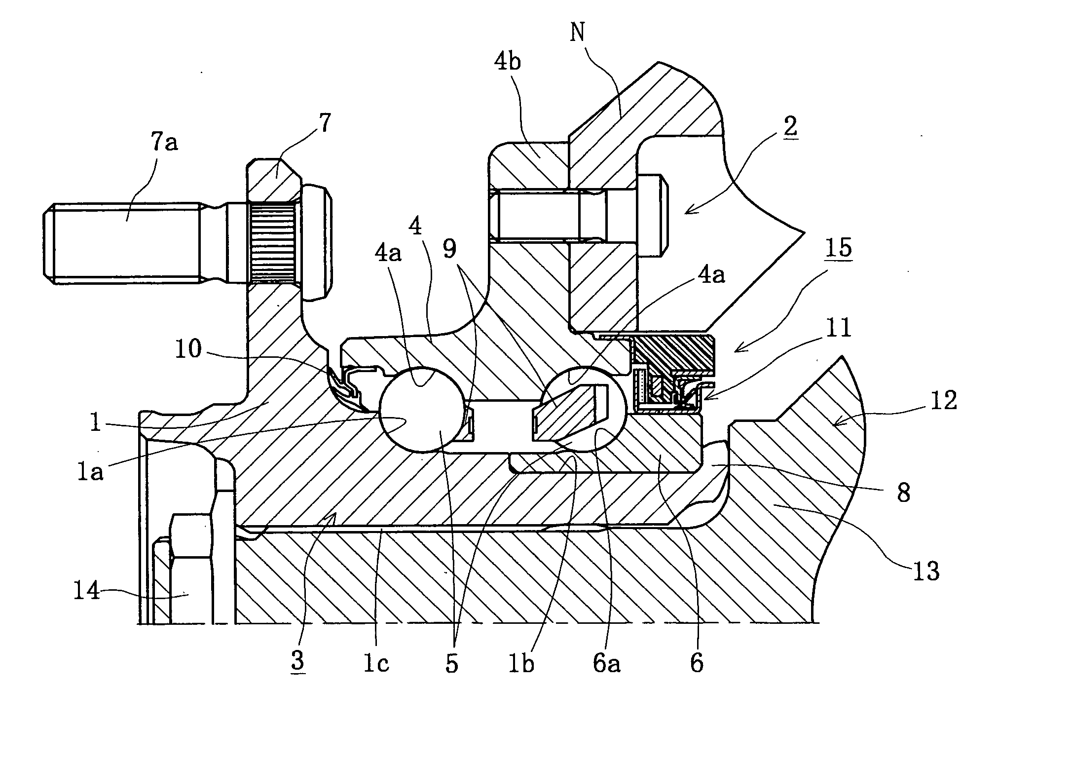
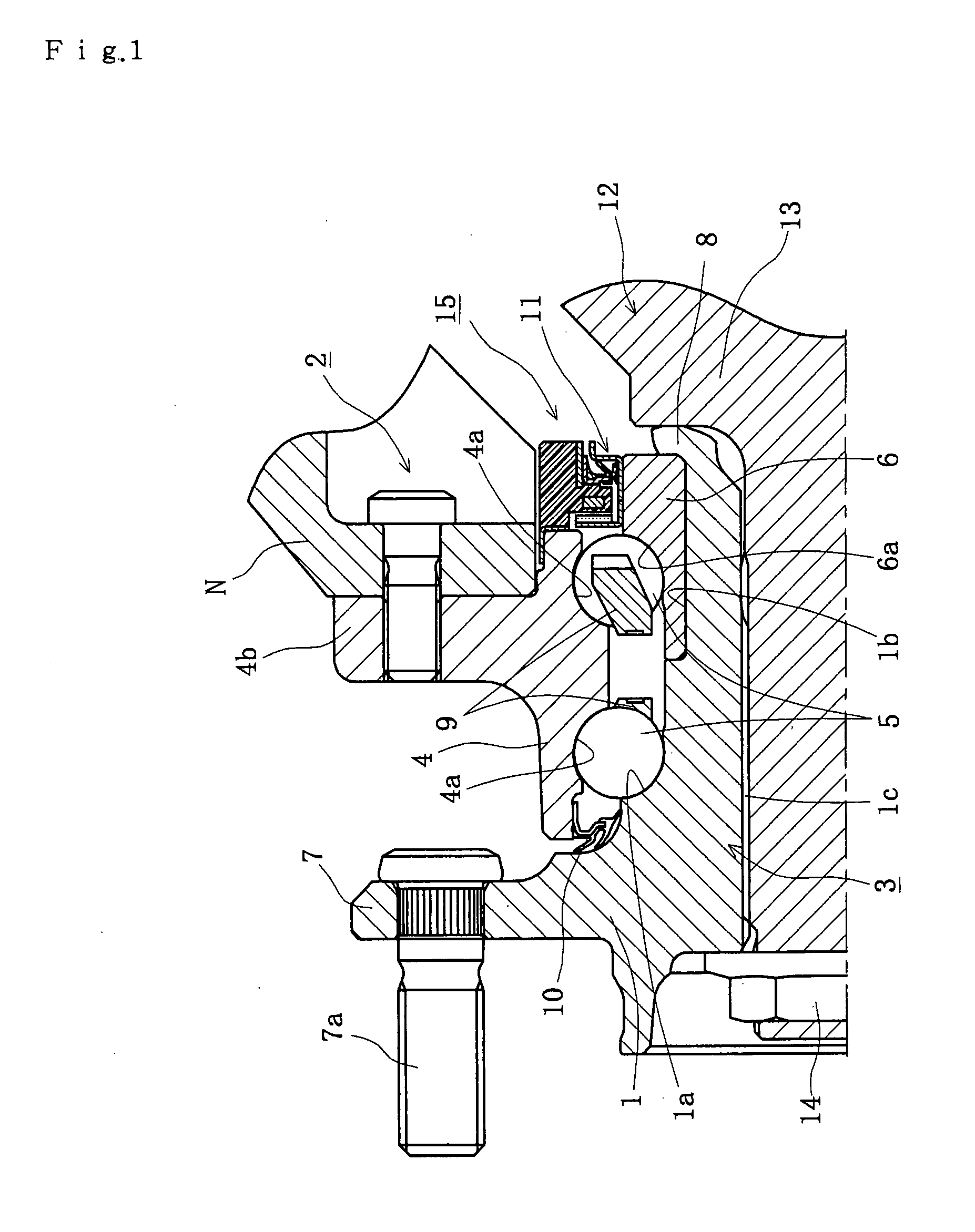
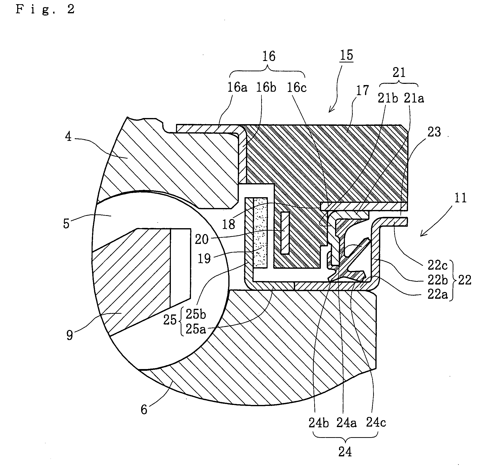
[0052]FIG. 1 is a longitudinal-section view of a wheel bearing apparatus with an incorporated wheel speed detecting apparatus. FIG. 2 is a partially enlarged longitudinal-section view of FIG. 1. In the description of the present invention, an outer side of a bearing apparatus, when it is mounted on a vehicle, is referred to as “outboard” side (the left side in a drawing). An inner side of a bearing apparatus, when it is mounted on a vehicle, is referred to as the “inboard” side (the right side in a drawing).

[0053] The wheel bearing apparatus with an incorporated wheel speed detecting apparatus is for a driving wheel where a wheel hub 1 and a double row rolling bearing 2 are formed as a unit arrangement. Thus, this structure is a so-called “third generation”.

[0054] The double row rolling bearing 2 includes an outer member 4, an inner member 3, and double row rolling elements (balls) 5 and 5. The outer member 4 is made of medium carbon steel including carbon of 0.40-0.80% by weight. ...

third embodiment

[0071] As can be clearly understood, according to this third embodiment, the shield 27 is arranged at the inboard side of the seal 11′. Thus, labyrinth seal 28, between the seal 11′ and the shield 27, labyrinth seal 29, between the shoulder 13 of the outer joint member 12 and the shield 27, and labyrinth seal 26 of the seal 11′ are formed. Accordingly, it is possible to prevent ingress of foreign matter from outside of the bearing apparatus, such as magnetic powder, into a space between the magnetic encoder 19 and the wheel speed sensor 20 even before the outer joint member 12 is inserted into the wheel hub 1. The ingress is prevented even though it includes a course where the bearing apparatus is transferred to an assembly line of a manufacturer of automobiles. It is also prevented under severe circumstances in real running conditions of the vehicle.

[0072]FIG. 5 is an enlarged view showing a fourth embodiment of the wheel bearing apparatus with an incorporated wheel speed detecting...

fourth embodiment

[0074] As can be clearly understood, according to this fourth embodiment, the shield 30 is arranged at the inboard side of the seal 11′. Thus, labyrinth seals 29 and 31 are formed between the shield 30 and the shoulder 13 of the outer joint member 12 and the end surface of the inner ring 6′ in addition to the labyrinth seal 26 of the seal 11′. Accordingly, it is possible to prevent ingress of foreign matter from outside of the bearing apparatus, such as magnetic powder, into a space between the magnetic encoder 19 and the wheel speed sensor 20 even before the outer joint member 12 is inserted into the wheel hub 1. The ingress is prevented even though it includes a course where the bearing apparatus is transferred to an assembly line of a manufacturer of automobiles. It is also prevented under severe circumstances in real running conditions of the vehicle.

[0075]FIG. 6 is a partially enlarged view of a fifth embodiment of a wheel bearing apparatus with an incorporated wheel speed dete...


PUM


Abstract

A wheel bearing apparatus with an incorporated wheel speed detecting apparatus has an outer member with double row outer raceway surfaces formed on its inner circumferential surface. An inner member includes a wheel hub with an integrally formed wheel mounting flange at one end. A cylindrical portion axially extends from the wheel mounting flange. An inner ring is fit onto the cylindrical portion of the wheel hub. Double row inner raceway surfaces, opposite to the double row outer raceway surfaces, are formed on the outer circumferential surfaces of the wheel hub and inner ring, respectively. Double row rolling elements are arranged between the outer and inner raceway surfaces. An encoder is mounted on the outer circumferential surface of the inner ring. An annular sensor holder is arranged on the end of the outer member opposite to the encoder. A wheel rotation speed detecting sensor is integrally molded with the sensor holder and arranged opposite to the encoder, via a predetermined radial gap. The encoder has an annular ring configuration with its characteristics alternately and equidistantly varying along its circumferential direction. A seal is arranged at the inboard side of the encoder via the sensor holder. The seal includes a first annular sealing plate and a second annular sealing plate. The first and second annular plates are mounted on the sensor holder and the inner ring, respectively, and opposite toward each other.

Description

CROSS-REFERENCE TO RELATED APPLICATIONS [0001] This application is a National Stage of International Application No. PCT / JP2005 / 16612, filed Sep. 9, 2005, which claims priority to Japanese Patent Application No. 2004-264194, filed Sep. 10, 2004; Japanese Patent Application No. 2004-273180, filed on Sep. 21, 2004; Japanese Patent Application No. 2004-294107, filed on Oct. 6, 2004; Japanese Patent Application No. 2004-300362, filed on Oct. 14, 2004; Japanese Patent Application No. 2004-300363, filed on Oct. 14, 2004; and Japanese Patent Application No. 2004-327307, filed on Nov. 11, 2004. The disclosures of the above applications are incorporated herein by reference. FIELD [0002] The present disclosure relates to a vehicle wheel bearing apparatus and, more particularly, to a wheel bearing apparatus with an incorporated wheel speed detecting apparatus to detect rotation speed of wheel of vehicle. BACKGROUND [0003] It is generally known for a wheel bearing apparatus which supports a veh...

Claims


Application Information

Patent Timeline
Patent Type & Authority Applications(United States)
IPC IPC(8): F16C41/04F16C13/00
CPCF16C19/186F16C41/007F16C2326/02F16C33/805G01P3/443G01P3/487F16C33/7886F16J15/326
Inventor SHIGEOKA, KAZUHISASUZUKI, SYOUGOONO, YUJIROKOMORI, KAZUOFUKADA, KIKUO
Owner NTN CORP
Why Eureka
Try Eureka