Instrument for minimal invasive surgery

a technology of minimal invasive surgery and instruments, applied in the field of medical forceps, can solve the problems of reduced stability, reduced thickness of surface layer, and complicated mechanics of toggle lever manufacture and assembly, and achieve the effect of reducing the number of required components

Active Publication Date: 2007-04-17
RICHARD WOLF GMBH
View PDF11 Cites 28 Cited by
  • Summary
  • Abstract
  • Description
  • Claims
  • Application Information

AI Technical Summary

Benefits of technology

[0018]Preferably, with this embodiment, there are formed two guide paths on two opposing sides of the insert. Thus only a single component is required in which both guide paths are formed for two movable jaw paths. In this manner, the number of required components may be reduced further.
[0019]The guide paths may be formed in one insulation element. For example, the insert or inser...

Problems solved by technology

The disadvantage of these coatings is the fact that they must have a certain layer thickness in order to ensure adequate insulation properties.
At the same time it is disadvantageous that the layer thickness on the surfaces is, for example, thicker than at the edges.
Furtherm...

Method used


Image

  • Instrument for minimal invasive surgery
  • Instrument for minimal invasive surgery
  • Instrument for minimal invasive surgery

Examples


Embodiment Construction

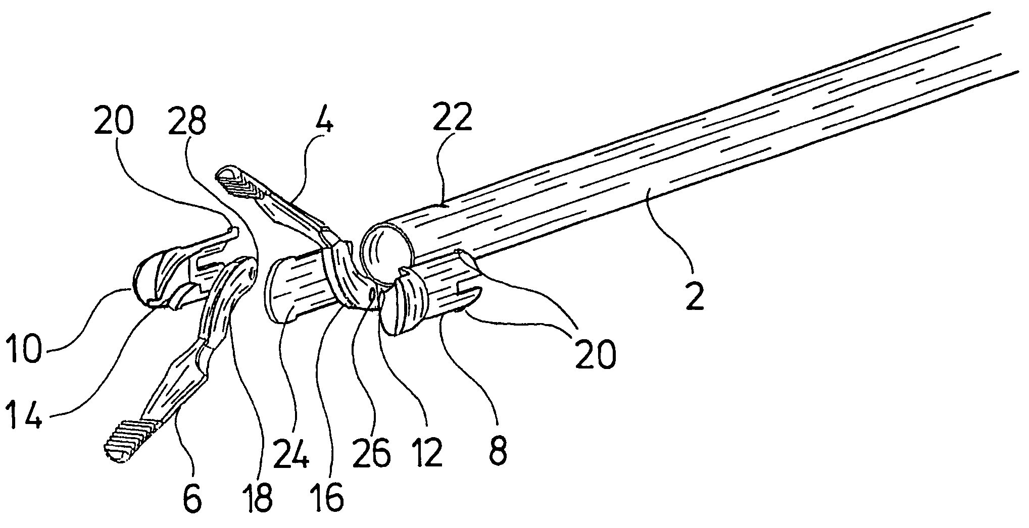
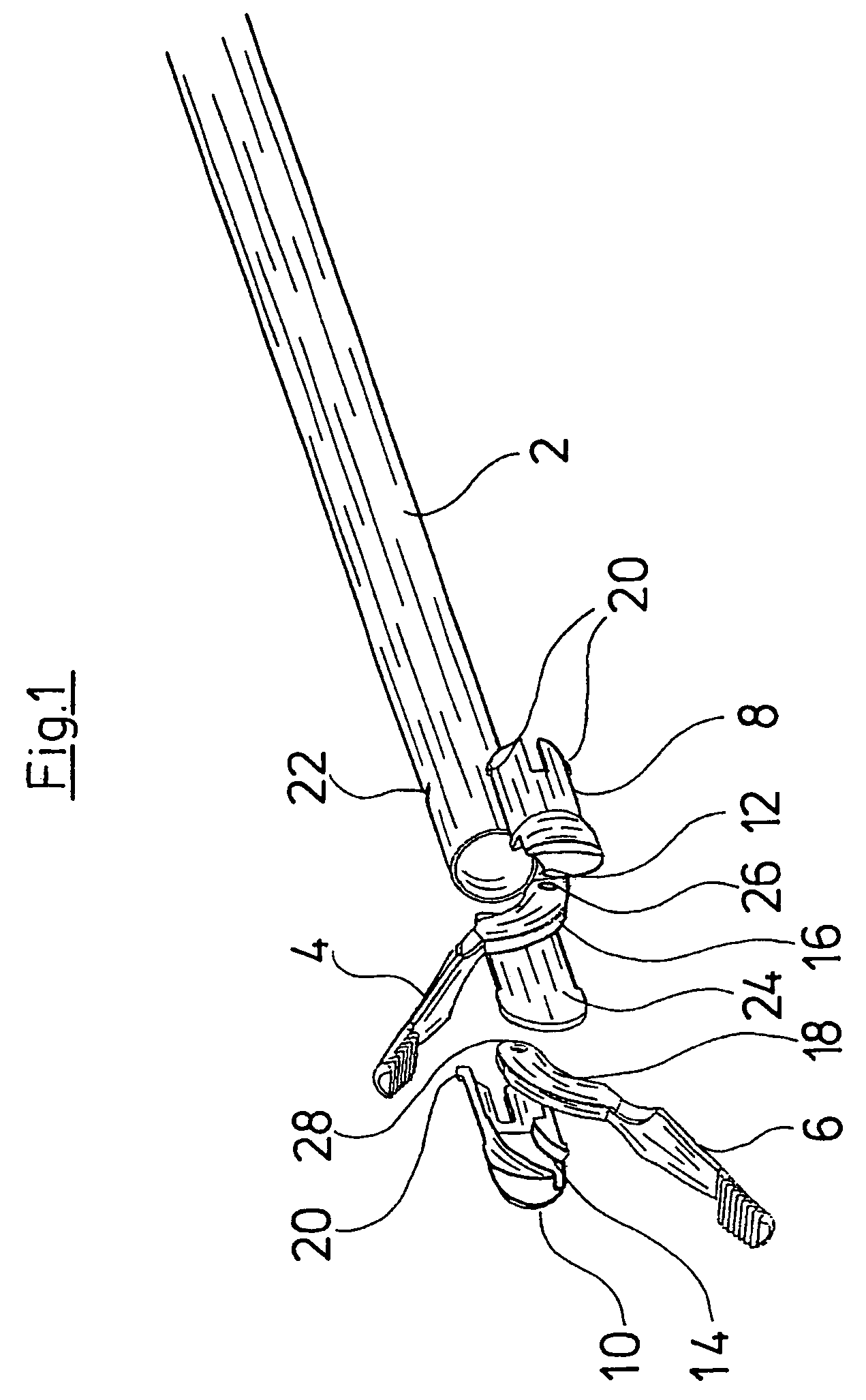
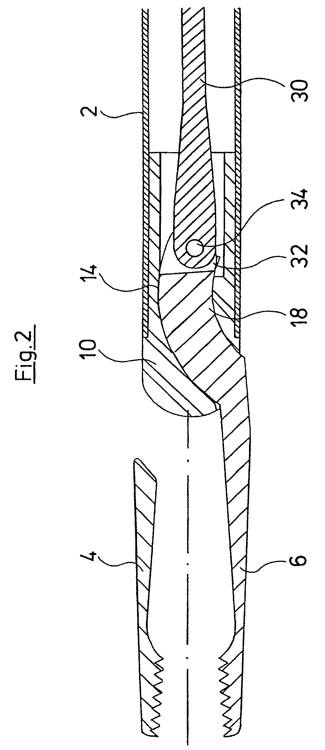
[0030]FIG. 1 shows an exploded view of the distal end of a forceps according to a first embodiment of the invention. The shown embodiment is a medical forceps designed as a bipolar coagulation gripping forceps. The forceps comprises a forceps shank 2 on whose distal end there is formed a forceps jaw, consisting of two movable jaw parts 4 and 6. The branches or jaw parts 4, 6 are movably guided in two inserts in the form of semi-shell elements 8 and 10. The distal ends of the jaw parts 4 and 6 may be designed in various manners. In the shown example they have serrated gripping surfaces. Alternatively, the jaw parts may also be designed as scissors. The proximal ends of the jaw parts 4, 6 are designed as linkage arms 16 and 18. The linkage arms 16 and 18 are curved in a circular arc shape. In the semi-shell elements 8 and 10 there are formed guide paths 12 and 14 in the form of grooves curved in a circular arc-shaped manner. The curvature of the guide paths 12, 14 corresponds to the a...


PUM


Abstract

A medical forceps has a forceps shank and a forceps jaw which comprises at least one movable jaw part, wherein the jaw part has a curved linkage arm at its proximal end. The linkage arm is movably guided in a curved guide path of an insert which is inserted into at least one receiver at the distal end of the forceps shank.

Description

BACKGROUND OF THE INVENTION[0001]The invention relates to a medical forceps, in particular for minimal invasive surgery.[0002]From German published patent application DE 197 34 781 A1, for example, there is known a bipolar gripping forceps for minimal invasive surgery. With this forceps the jaw parts of the forceps jaw are opened and closed via toggle lever elements by way of moving an actuation rod arranged in the inside of the forceps shank. In order to insulate those parts of the jaw part conducting current these parts have an insulation coating. The disadvantage of these coatings is the fact that they must have a certain layer thickness in order to ensure adequate insulation properties. At the same time it is disadvantageous that the layer thickness on the surfaces is, for example, thicker than at the edges. Furthermore, due to the relatively thick insulation layers the wall thickness of the individual parts consisting of metal must be reduced, by which means the stability is re...

Claims


Application Information

Patent Timeline
IPC IPC(8): A61B18/18A61B17/28A61B18/14
CPCA61B17/29A61B18/1445A61B2017/2934
Inventor WAGNER, CARL-SEBASTIANDINGLER, ANDREASBARTOLI, JOSEF
Owner RICHARD WOLF GMBH
Why Eureka
Try Eureka