Switching Transformer

a transformer and switching technology, applied in the direction of magnets, cores/yokes, magnets, etc., can solve the problems of high cost of mass production of products, complicated assembling, and high cost of assembling, so as to improve efficiency, increase the coupling factor, and improve the workability of assembling

Inactive Publication Date: 2009-09-17
TAMURA KK
View PDF2 Cites 22 Cited by
  • Summary
  • Abstract
  • Description
  • Claims
  • Application Information

AI Technical Summary

Benefits of technology

[0020]According to the present invention, since the coils are wound around the outer circumference of the center-leg core protruding from the upper surface of the terminal block 1, the assembling workability is improved and the distance from the center part of the center-leg core to the coil is made shorter, leading to an increase in the coupling factor, as a result of which, there are effects that the efficiency is improved and power is obtained. In addition to this advantage of an increase in productivity and performance, the nonuse of a coil bobbin with a winding drum part ensures a small size, and the consumption of electric wires, insulating tapes and so on decreases. In addition, because the terminal block does not have a winding drum part, the amount of the material for the terminal block is reduced, enabling the costs to be reduced.
[0021]Because the center-leg core is supported with the rib, it is possible to stably support the center-leg core.
[0022]Furthermore, because the side-leg cores of the C-type core are disposed in the notches of the terminal block to ensure that these side-leg cores do not project outside of the terminal block, size reduction is made possible.

Problems solved by technology

Therefore, the consumption of the electric wires, insulating tapes and so on to be wound around the outer circumference of the winding drum pan increases, in proportion to which the cost gets higher, leading to a considerably high cost in the mass production of the products.
However, the above-described conventional example had a problem that, in attaching the insulating plate 100, it is necessary to bend and mount the insulating plate 100 to the coil-placing bottom portion 102, and hence it requires the bending process as well as the work of attaching the electrodes 104 as terminals respectively at four places of the insulating plate 100, so, the assembling is very complicated.
In this respect, also, the conventional example had a problem that the workability is very low.

Method used


Image

  • Switching Transformer
  • Switching Transformer
  • Switching Transformer

Examples


embodiment 1

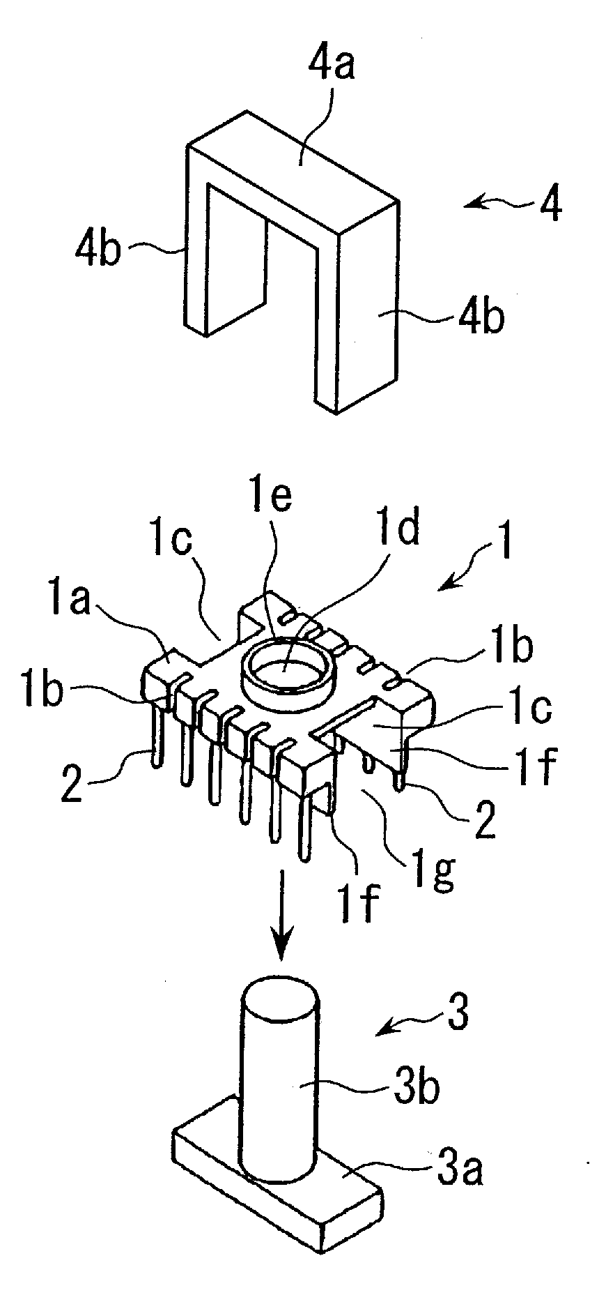
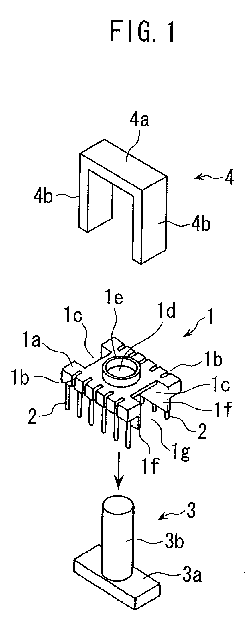
[0055]FIG. 1 is an exploded perspective view of Embodiment 1 of the present invention.

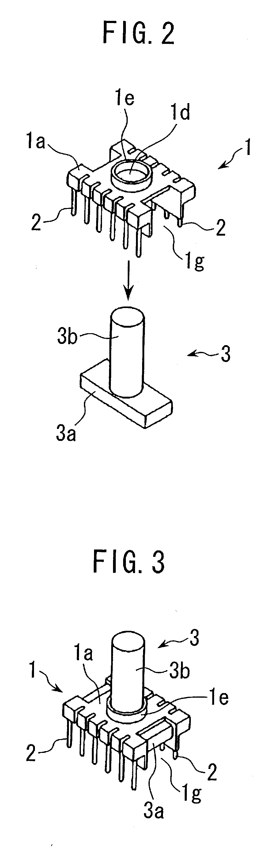
[0056]Without an use of a conventional coil bobbin with a winding drum part, the switching transformer of the present invention is configured with, as its main components, a terminal block 1 which has terminals 2 at both end portions of the lower surface in the illustrated condition and whose upper surface 1a is almost flat, a center-leg-having core 3 which is incorporated from the lower side in the illustrated condition and has a substantially T-shaped vertical cross section, and a substantially inverted U-shaped, side-leg-having, C-type core 4 that is incorporated from the upper side and whose side legs are placed on respective end portions of the top surface of the core.

[0057]The center-leg-having core 3, which is made of ferrite, is composed or an I-shaped core body 3a and a cylindrical center leg 3b provided in a standing manner on the center part of the top surface of this core body 3a.

[0058...


PUM

PropertyMeasurementUnit
thicknessaaaaaaaaaa
outer circumferenceaaaaaaaaaa
circumferenceaaaaaaaaaa

Abstract

There is provided a switching transformer which enables material costs to be reduced while the performance to be improved, permitting cost and size reductions, and which is suitable for mass production by ensuring good assemblability. Instead of using a conventional coil bobbin having a winding drum part, a center-leg-having core 3 having the shape of a substantially inverted T is integrated with a terminal block 1 having a substantially flat upper surface and terminals implanted in a lower surface. An electric wire 6a is wound around the outer circumference of a center-leg core 3b protruding from the upper surface 1a of the terminal block 1, thereby a coil 6 is mounted. A C-type core 4 is built into this assembly to form a switching transformer.

Description

TECHNICAL FIELD[0001]The present invention relates to a small switching transformer.BACKGROUND ART[0002]Conventionally, this type of switching transformer generally uses a coil bobbin in which there is formed, at an end of a hollow and cylindrical winding drum part, a terminal block having terminals. And, the switching transformer is configured with coils wound around the outer circumference of the winding drum part of this coil bobbin, and with a core having a center leg inserted in the winding drum part.[0003]In the above-described conventional switching transformer with a configuration in which electric wires are wound around the outer circumference of the hollow winding drum part of a coil bobbin, as described above, there is a slight gap between the outer circumference of the center leg of the core inserted into the winding drum part and the inner circumferential surface of the winding drum part. Further, due to the thickness of the winding drum part of approximately 1 mm, the ...

Claims


Application Information

Patent Timeline
Patent Type & Authority Applications(United States)
IPC IPC(8): H01F27/29H01F41/02
CPCH01F3/10H01F5/02H01F27/027H01F27/266Y10T29/49071H01F41/0612H01F41/0687H01F2005/043H01F27/325H01F41/064H01F41/098
Inventor WATANABE, OSAMU
Owner TAMURA KK
Why Eureka
Try Eureka